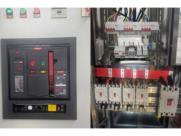
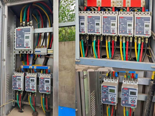
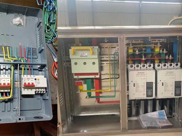
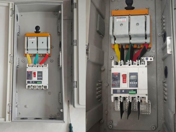
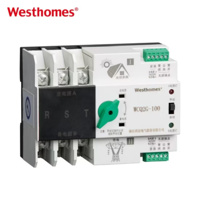
WCQ2C Moulded case circuit breaker
WCQ2C is one of updated type MCCBs researched and developed by the company by using advanced design and manufacture technology internationally.
Get quick appointment for technical support!

WCQ2C series MCB is one of updated type MCCBs researched and developed by the company by using advanced design and manufacture technology internationally.



WCQ2C is one of updated type MCCBs researched and developed by the company by using advanced design and manufacture technology internationally.
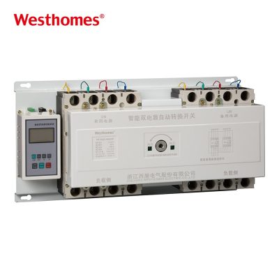
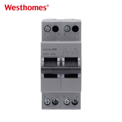
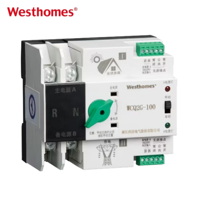
WCQ2C series double power supplies automatic transfer switch (ATS) applies to AC50Hz, rated operation voltage 400V, rated operation current 16A to 2000A, to two circuits power supply of emergency power supply system. It can be set as manual of the mutual transfer between frequent-use and backup power supply, as circuit controlling switch of control, signal, and interlock functions. Some types of the product have communication ports to make it realisable of remote control and unattended substation to the user. It applies to residence community, hospital, mall, airport, etc.,
The ATS meets standards IEC/EN60947 and GB/T14048.11.
| Pole | 2P,3P, 4P |
| Voltage | AC400V |
| Icm | 7.5KA-63KA |
| Inm(A) | 63 |
| In(A) | 6-63 |
| Model | WCQ2C | |
| Rated short circuit breaking capacity | 5kA | |
| Rated short circuit connecting capacity | 7.5kA | |
| Transfer time | ≤3S | |
| Controlling voltage of changeover switch | AC230V | |
| Mechanical life | 3000 times | |
| Electrical life | 1500 times | |
| Rated insulation voltage | U=690V | |
| Rated operation current | 10A, 16A, 20A, 25A, 32A, 40A, 50A, 63A | |
| Usage catagory | AC-33B | |
| Test condition of connecting and breaking | I/Ie | 6.0 |
| U/Ue | 1.05 | |
| Cos4 | 0.5 | |
| Power-on time | 0.05s | |
| Circle | ≤5min | |
| Operation circle times | 12 | |

A 2-pole ATS automatically switches a two-conductor load (typically a 230V single-phase or a split-phase application) between two power sources, such as utility and a standby generator. It opens the live and neutral (or two legs) of one source before closing the other, preventing back-feed. It is commonly used where the load is single-phase but the system nominal voltage is rated at 400V class.
An electronic controller monitors the main supply; when voltage falls outside the set window (under-voltage, over-voltage, or loss of phase), it waits a pre-set delay, triggers the standby source, and—once its voltage is stable—swaps the contacts. When the main returns and stays stable for the return delay, it transfers back and shuts down the standby. The mechanical interlock guarantees the two sources can never be connected together.
Even though it switches two conductors, the device is rated at the 400V low-voltage class, meaning its insulation and dielectric withstand are designed for standard mains systems. In practice a 2P unit is usually applied to 230V phase-to-neutral single-phase loads or to switch one phase pair. Always confirm the rated operational voltage matches the actual source-to-source and source-to-earth voltages before installation.
Two source inputs (main and standby) each occupy two terminals, and two load conductors go to the common output. Compared with a 4P ATS used for three-phase loads, a 2P unit only switches the two conductors needed for a single-phase circuit. Correct polarity/phase orientation and a reliable earth connection are still required, and the neutral should be switched together with the line to keep isolation.
The contact movement itself is near-instantaneous (a few tens of milliseconds), but the controller introduces intentional delays: a mains-fault detection delay, a generator-start and stabilization delay, and a return delay. These are user-adjustable so the switch does not react to brief voltage sags. Total interruption time depends on generator warm-up settings, often several seconds for engine-driven sets.
It is ideal for single-phase backup in homes, small shops, offices, villas, and standalone equipment such as security systems, water pumps, or small HVAC units. Where the building has a single-phase utility supply and a single-phase generator, a 2P ATS provides fully automatic backup without over-specifying a three-phase device. It is also used to select between two feeders in critical single-phase circuits.
Yes—the controller includes LEDs or an indicator that shows which source is live, fault conditions (over/under voltage, phase loss), and transfer status. This makes it easy to diagnose whether an outage was on the main or standby side. More advanced versions add adjustable delay and threshold settings accessible via buttons or a small display.
Mount the ATS on a DIN rail or panel inside the distribution board, connect main and standby inputs and the load output with correctly sized conductors, and earth the enclosure. A qualified electrician sets the voltage thresholds and time delays and verifies the mechanical interlock. Keep cable bending clear of the moving contacts and respect the recommended clearance around the device.
It is designed to IEC 60947-6-1, the product standard for automatic transfer switch equipment within low-voltage switchgear and controlgear. The standard defines the transfer function, utilized categories, contact positions, and safety tests (including no-paralleling of sources). CE and regional certification marks are applied as required by the target market.
Test the transfer function periodically—for example twice a year—by simulating a main supply loss and confirming the standby starts and takes over within the programmed time. Inspect terminals for tightness, keep the panel clean and dry, and exercise the manual operation handle if fitted. Record test results; if the switch fails to transfer or shows an alarm, a qualified technician should inspect the controller and contacts.
* indicates a required field

 2 MB