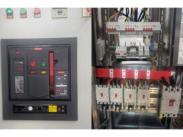
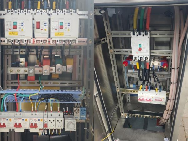
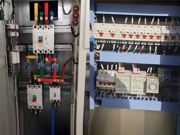
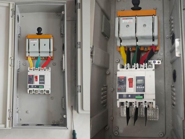
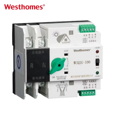
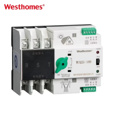
WCQ2G Moulded case circuit breaker
WCQ2G is one of updated type MCCBs researched and developed by the company by using advanced design and manufacture technology internationally.
Get quick appointment for technical support!

WCQ2G series MCB is one of updated type MCCBs researched and developed by the company by using advanced design and manufacture technology internationally.



WCQ2G is one of updated type MCCBs researched and developed by the company by using advanced design and manufacture technology internationally.
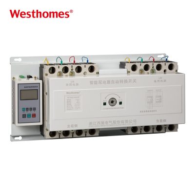
WCQ2G series double power supplies automatic transfer switch (ATS) applies to AC50Hz, rated operation voltage 400V, rated operation current 16A to 2000A, to two circuits power supply of emergency power supply system. It can be set as manual of the mutual transfer between frequent-use and backup power supply, as circuit controlling switch of control, signal, and interlock functions. Some types of the product have communication ports to make it realisable of remote control and unattended substation to the user. Itapplies to residence community, hospital, mall, airport, etc.,
The ATS meets standards IEC/EN60947 and GB/T14048.11.

The WCQ2G automatic transfer switch works reliably under the following conditions:
Altitude not exceeding 2000 meters
Ambient temperature not higher than 40℃,not lower than-5℃,relative humidity not more than 95%.
No explosion hazardous medium environment
No rain or snow attack environment
Note:If the switch is expected to be used in conditions where the ambient air temperatureis higher than+40℃or lower than -5~-45,the user should explain to the manufacturer.
| Pole | 3P, 4P |
| Voltage | AC230V/400V |
| Icm | 8KA-26KA |
| Inm(A) | 100,160,250,630 |
| In(A) | 16-630 |
| Conventional thermal current Ith (A) | 100 | 160 | 250 | 630 | 1600 | |||||||||||
| Rated current In (A) | 20 | 40 | 63 | 80 | 125 | 160 | 200 | 250 | 400 | 630 | 800 | 1000 | 1250 | 1600 | ||
| Rated insulation voltage Ui (V) | 690 | 690 | 690 | 690 | 690 | 690 | 690 | 690 | 690 | 690 | 690 | 690 | 690 | 690 | ||
| Dielectric strength (V) | 5000 | 5000 | 5000 | 5000 | 5000 | 5000 | 5000 | 5000 | 8000 | 8000 | 10000 | 10000 | 10000 | 10000 | ||
| Rated impulse withstand voltage Uimp (kV) mounting catagory (IV) | 8 | 8 | 8 | 8 | 8 | 8 | 8 | 8 | 12 | 12 | 12 | 12 | 12 | 12 | ||
| Rated service current Ie (A) | 400V | AC-31 | 20 | 40 | 63 | 80 | 125 | 160 | 200 | 250 | 400 | 630 | 800 | 1000 | 1250 | 1600 |
| AC-33 | 20 | 40 | 63 | 80 | 125 | 160 | 200 | 250 | 400 | 630 | 800 | 1000 | 1250 | 1600 | ||
| AC-35 | 20 | 32 | 40 | 63 | 80 | 125 | 160 | 200 | 250 | 400 | 630 | 800 | 1000 | 1250 | ||
| 230V | DC-31 | 20 | 40 | 63 | 80 | 125 | 160 | 200 | 250 | 400 | 630 | 800 | 1000 | 1250 | 1600 | |
| DC-33 | 20 | 40 | 63 | 80 | 125 | 160 | 200 | 250 | 400 | 630 | 800 | 1000 | 1250 | 1600 | ||
| DC-35 | 20 | 32 | 40 | 63 | 80 | 125 | 160 | 200 | 250 | 400 | 630 | 800 | 1000 | 1250 | ||
| Power of motor P (400V) (kW) | 10 | 25 | 25 | 30 | 63 | 80 | 100 | 132 | 220 | 280 | 450 | 560 | 560 | 560 | ||
| Rated short time withstand current Icw (kA Rms) 0.1S/1S | 3/2.0 | 4/4.2 | 5/2.5 | 9/5 | 20/10 | 20/10 | 25/12 | 25/12 | 40/20 | 50/25 | 90/50 | 90/50 | 90/50 | 90/50 | ||
| Rated breaking capacity (kA Rms) AC35 400V | 160 | 320 | 500 | 640 | 1000 | 1000 | 1600 | 1600 | 3200 | 3200 | 8000 | 8000 | 8000 | 8000 | ||
| Rated connecting capacity (kA Rms) AC35 400V | 200 | 400 | 630 | 800 | 1250 | 1250 | 2000 | 2000 | 4000 | 4000 | 10000 | 10000 | 10000 | 10000 | ||
| Rated short circuit breaking capacity Icm (kA peak value) | 8 | 8 | 10 | 10 | 12 | 12 | 17 | 17 | 30 | 30 | 50 | 50 | 50 | 50 | ||
| Mechanical life (circulation operation times) | 100000 | 100000 | 100000 | 100000 | 100000 | 100000 | 100000 | 100000 | 5500 | 5500 | 4000 | 4000 | 4000 | 3000 | ||
| Electrical life | Cos Φ = 0.95 AC31 | 2500 | 2500 | 2500 | 1500 | 1500 | 1500 | 1500 | 1500 | 750 | 750 | 600 | 600 | 600 | 450 | |
| Cos Φ = 0.65 AC33 | 1500 | 1500 | 1500 | 1000 | 1000 | 1000 | 1000 | 1000 | 500 | 500 | 400 | 400 | 400 | 300 | ||
| Cos Φ = 0.35 AC35 | 750 | 750 | 750 | 500 | 500 | 500 | 500 | 500 | 250 | 250 | 200 | 200 | 200 | 150 | ||
| Transfer time | I-O-II or II-O-I (s) | 1.0 | 1.0 | 1.0 | 1.0 | 1.0 | 1.0 | 1.1 | 1.1 | 1.2 | 1.2 | 1.2 | 1.2 | 1.2 | 1.2 | |
| I-O or II-O-I (s) | 0.5 | 0.5 | 0.5 | 0.6 | 0.6 | 0.6 | 0.7 | 0.7 | 0.8 | 0.8 | 0.8 | 0.8 | 0.8 | 0.8 | ||
| Motor energy consumption | 24V (DC) (w) | 40 | 40 | 40 | 75 | 75 | 75 | 75 | 75 | 90 | 90 | 120 | 120 | 120 | 120 | |
| 230V (AC) (w) | 40 | 40 | 40 | 75 | 75 | 75 | 75 | 75 | 90 | 90 | 120 | 120 | 120 | 120 | ||
| Operation torque (Nm) | 12 | 12 | 12 | 19 | 19 | 19 | 26 | 26 | 39 | 39 | 39 | 39 | 39 | 60 | ||
| Weight (kg) | Three poles | 7.2 | 7.2 | 7.2 | 8 | 8 | 10 | 10 | 22 | 22 | 22 | 34 | ||||
| Four poles | 4.2 | 4.3 | 4.4 | 7.5 | 7.5 | 7.5 | 9 | 9 | 11 | 11 | 28 | 28 | 28 | 40 | ||

ATS stands for Automatic Transfer Switch. It automatically moves a load between two independent power sources—typically a utility (mains) supply and a generator or backup supply—without an operator. The WCQ2G is an integrated, motorized transfer switching device that continuously monitors both sources and transfers the load when the preferred supply fails.
The WCQ2G integrates the switch and logic control into one electromechanical unit, so no separate controller is required. It provides voltage detection, built-in electrical and mechanical interlocks, and supports automatic, motorized remote, and emergency manual operation. It also offers control, signal, and interlock functions, and some versions include communication ports.
When the controller detects the mains voltage falling outside the set limits, it opens the main contact and transfers the load to the backup source. If the backup is a generator, the controller also sends a start signal and waits until the generator voltage and frequency are stable before transferring. When mains returns and stays stable through the retransfer delay, it switches back.
Poles count the number of conductors switched. 1P is for single-phase live-only, 2P switches live and neutral in a single-phase system, 3P switches the three phases in a three-phase three-wire system, and 4P switches three phases plus the neutral in a three-phase four-wire system. Choose 3P/4P for three-phase loads and 1P/2P for single-phase distribution.
The WCQ2G is designed for AC 50 Hz systems at a rated operational voltage of 400 V, with rated operational currents typically from 16 A up to the series maximum. The 400 V class matches common low-voltage three-phase distribution used in buildings, factories, and utility connections.
Yes. The controller can output a relay contact signal to start the standby generator when mains failure is detected. It then waits for the generator output to reach a stable voltage and frequency window before transferring the load, and signals the generator to cool down and stop after retransfer.
The physical switching mechanism itself operates in a fraction of a second, while the full mains-to-generator sequence—detection, generator start, stabilization, and transfer—typically takes several seconds depending on the generator warm-up. Transfer delay and retransfer delay are adjustable on the controller to prevent unstable or rapid cycling.
It is used anywhere supply continuity matters, such as hospitals, data centers, commercial buildings, shopping malls, airports, factories, and residential communities. It is commonly applied at the main or sub-main distribution feeding critical or emergency loads.
The WCQ2G meets IEC/EN 60947-6-1 (Transfer Switching Equipment) and the corresponding Chinese standard GB/T 14048.11. IEC 60947-6-1 covers transfer switching equipment rated up to 1000 V AC used to ensure continuity of supply and manage energy between sources.
Perform periodic visual and mechanical inspection, check terminals for tightness, and exercise the mechanism through the manual or test transfer cycle. Verify that voltage sensing, generator start contacts, and interlocks function correctly, and confirm the set delays and thresholds. Keep the enclosure clean and dry, and record test results for compliance records.
* indicates a required field

 2 MB