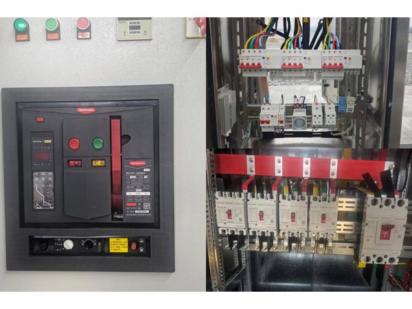
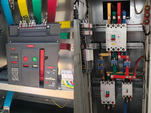
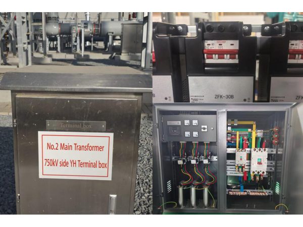
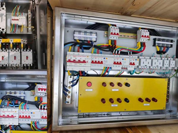
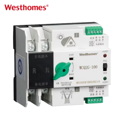
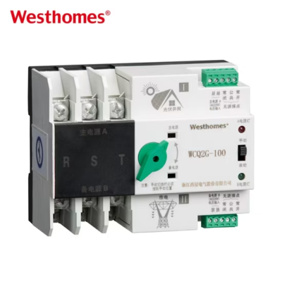
WCQ2C Moulded case circuit breaker
WCQ2C is one of updated type MCCBs researched and developed by the company by using advanced design and manufacture technology internationally.
Get quick appointment for technical support!

WCQ2C series MCB is one of updated type MCCBs researched and developed by the company by using advanced design and manufacture technology internationally.



WCQ2C is one of updated type MCCBs researched and developed by the company by using advanced design and manufacture technology internationally.
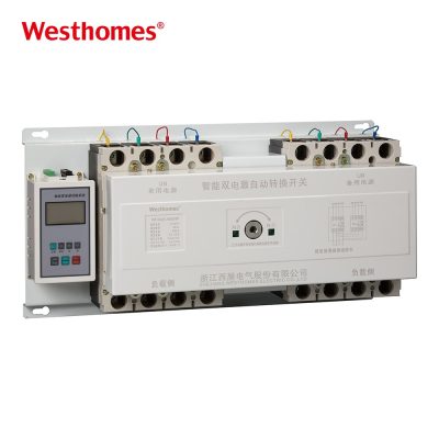
WCQ2C series double power supplies automatic transfer switch (ATS) applies to AC50Hz, rated operation voltage 400V, rated operation current 16A to 2000A, to two circuits power supply of emergency power supply system. It can be set as manual of the mutual transfer between frequent-use and backup power supply, as circuit controlling switch of control, signal, and interlock functions. Some types of the product have communication ports to make it realisable of remote control and unattended substation to the user. It applies to residence community, hospital, mall, airport, etc.,
The ATS meets standards IEC/EN60947 and GB/T14048.11.
| Pole | 2P,3P, 4P |
| Voltage | AC400V |
| Icm | 7.5KA-63KA |
| Inm(A) | 63 |
| In(A) | 6-63 |
| Model | WCQ2C | |
| Rated short circuit breaking capacity | 5kA | |
| Rated short circuit connecting capacity | 7.5kA | |
| Transfer time | ≤3S | |
| Controlling voltage of changeover switch | AC230V | |
| Mechanical life | 3000 times | |
| Electrical life | 1500 times | |
| Rated insulation voltage | U=690V | |
| Rated operation current | 10A, 16A, 20A, 25A, 32A, 40A, 50A, 63A | |
| Usage catagory | AC-33B | |
| Test condition of connecting and breaking | I/Ie | 6.0 |
| U/Ue | 1.05 | |
| Cos4 | 0.5 | |
| Power-on time | 0.05s | |
| Circle | ≤5min | |
| Operation circle times | 12 | |
| Specification | Model of circuit breaker | Frame size current (A) | Rated operation current (A) | Breaking current (kA) | Rated service voltage (V) | Insulation voltage (V) | Frequency (Hz) | Transfer time | Rated operation voltage of controller (V) | Mechanical life |
| WCQ2A(1)-63/3 | WCM1 series | 63 | 6, 10, 20, 25, 32, 40, 50, 63 | Take specific type of circuit breaker specification for reference | 400 | No flash, no spark-over within 1min 2500V | 50~60 | 0-30 seconds adjustable | AC230V | 5000 times |
| WCQ2A(1)-63/4 | ||||||||||
| WCQ2A(1)-100/3 | 100 | 10, 20, 25, 32, 40, 50, 63, 80, 100 | ||||||||
| WCQ2A(1)-100/4 | ||||||||||
| WCQ2A(1)-225/3 | 225 | 100, 125, 140, 160, 180, 200, 225 | ||||||||
| WCQ2A(1)-225/4 | ||||||||||
| WCQ2A(1)-400/3 | 400 | 200, 250, 315, 400 | ||||||||
| WCQ2A(1)-400/4 | ||||||||||
| WCQ2A(1)-630/3 | 630 | 250, 315, 400, 500, 630 | ||||||||
| WCQ2A(1)-630/4 | ||||||||||
| WCQ2A(1)-800/3 | 800 | 630, 700, 800 | ||||||||
| WCQ2A(1)-800/4 | ||||||||||
| WCQ2A(1)-1250/3 | 2000 | 1250, 1600, 2000 | ||||||||
| WCQ2A(1)-2000/3 |

The WCQ2C is a range of automatic transfer switches designed for low-voltage dual-power applications, available in 1P, 2P, 3P, and 4P configurations to match single- and three-phase loads. It combines a fast, mechanically interlocked switching mechanism with an intelligent monitoring controller. The "air" designation refers to air-break contact switching—arcs are extinguished in air rather than in oil or gas—typical of modular ATS products.
"Air" means the contacts open and close in open air, with the switching arc extinguished by the contact geometry and airflow rather than sealed in an oil or SF6 chamber. This is standard for low-voltage, low-current ATS units and provides reliable, maintenance-free switching for 50/60Hz mains. It keeps the device compact and DIN-rail mountable while meeting the required breaking and making capacity.
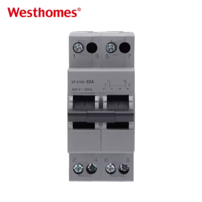
Select poles to match the load and system: 1P for a single line transfer, 2P for single-phase (line + neutral) loads, 3P for three-phase loads without switched neutral, and 4P for three-phase loads where the neutral must also be switched and isolated. Using the correct pole count prevents back-feed and ensures both sources are fully separated. Most three-phase, four-wire installations require a 4P unit.
The controller monitors both main and standby voltages. On main failure (under/over voltage, phase loss), it waits a programmable delay, signals the standby source (e.g., generator), and—once the standby is stable—operates the double-throw contacts to the standby. On main restoration, after a return delay it transfers back and stops the standby. A hard mechanical interlock prevents both sources from ever closing simultaneously.
The contact transfer itself is very fast—typically within tens of milliseconds—because the mechanism is motor or solenoid driven. However, the overall interruption time a user experiences is dominated by the adjustable generator-start and warm-up delays, which can be set from a few seconds to tens of seconds. The fast contact action minimizes the dead time for loads that can ride through short outages.
Yes, the controller has auxiliary output contacts designed to start/stop an engine generator set. When the main supply fails, the start contact closes; when the main returns and the transfer-back sequence is complete, the stop contact opens. This removes the need for a separate start relay and enables a fully unattended backup system. Verify the contact rating against the generator's starter circuit.
It is used in homes, villas, small offices, shops, workshops, and light commercial buildings that need automatic backup from a generator or a second utility feeder. It also serves critical loads such as pumps, elevators (smaller ones), lighting, and security systems where a blackout cannot be tolerated. The range of pole options covers single-phase residential through to three-phase small commercial loads.
Mount it on a 35mm DIN rail in a distribution board, connect the main and standby sources to their labelled inputs, the load to the common output, and earth the panel. A qualified electrician sets voltage thresholds, delays, and the generator signal wiring, and confirms the phase sequence for three-phase units. Upstream breakers on each source should be coordinated with the ATS current rating.
The WCQ2C is built to IEC 60947-6-1, which specifies requirements for automatic transfer switch equipment in low-voltage systems. The standard covers class designations (such as PC-class devices without overload protection, or CB-class incorporating breakers), contact reliability, interlocking, and endurance. Compliance allows use on export projects requiring IEC-based design.
Perform an annual or semi-annual simulated transfer test by disabling the main supply and observing the start, transfer, and return sequence. Re-torque terminals, check the controller indicators for alarms, and keep the panel dry and dust-free. If a manual operating handle is provided, exercise it occasionally to keep the mechanism free. Any failed transfer, repeated nuisance tripping, or abnormal noise should be inspected by a qualified technician.
* indicates a required field

 2 MB