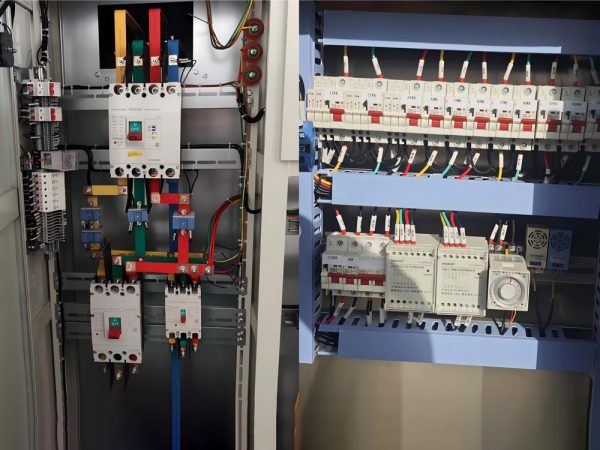
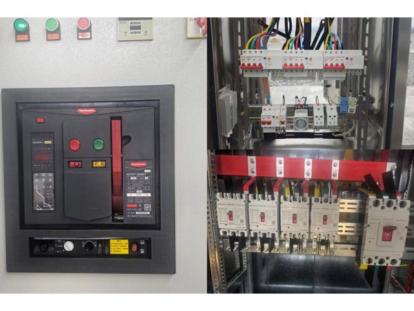
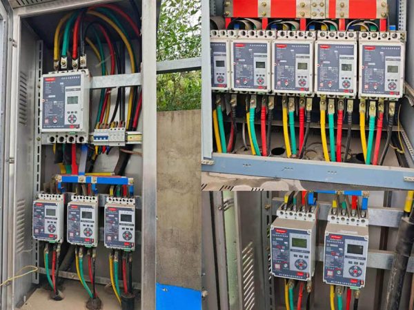
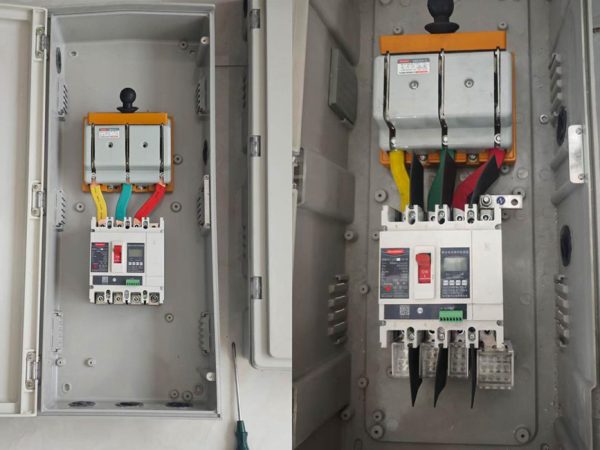
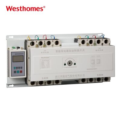
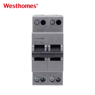
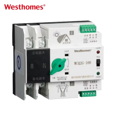
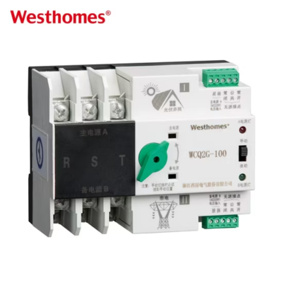
WCQ2C Moulded case circuit breaker
WCQ2C is one of updated type MCCBs researched and developed by the company by using advanced design and manufacture technology internationally.
Get quick appointment for technical support!

WCQ2C series MCB is one of updated type MCCBs researched and developed by the company by using advanced design and manufacture technology internationally.



WCQ2C is one of updated type MCCBs researched and developed by the company by using advanced design and manufacture technology internationally.
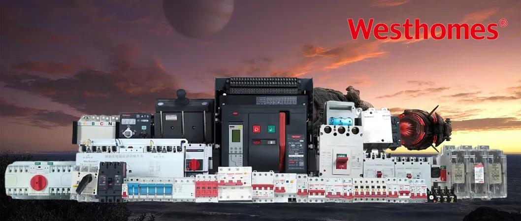
WCQ2C series double power supplies automatic transfer switch (ATS) applies to AC50Hz, rated operation voltage 400V, rated operation current 16A to 2000A, to two circuits power supply of emergency power supply system. It can be set as manual of the mutual transfer between frequent-use and backup power supply, as circuit controlling switch of control, signal, and interlock functions. Some types of the product have communication ports to make it realisable of remote control and unattended substation to the user. It applies to residence community, hospital, mall, airport, etc.,
The ATS meets standards IEC/EN60947 and GB/T14048.11.
| Pole | 2P,3P, 4P |
| Voltage | AC400V |
| Icm | 7.5KA-63KA |
| Inm(A) | 63 |
| In(A) | 6-63 |
| Model | WCQ2C | |
| Rated short circuit breaking capacity | 5kA | |
| Rated short circuit connecting capacity | 7.5kA | |
| Transfer time | ≤3S | |
| Controlling voltage of changeover switch | AC230V | |
| Mechanical life | 3000 times | |
| Electrical life | 1500 times | |
| Rated insulation voltage | U=690V | |
| Rated operation current | 10A, 16A, 20A, 25A, 32A, 40A, 50A, 63A | |
| Usage catagory | AC-33B | |
| Test condition of connecting and breaking | I/Ie | 6.0 |
| U/Ue | 1.05 | |
| Cos4 | 0.5 | |
| Power-on time | 0.05s | |
| Circle | ≤5min | |
| Operation circle times | 12 | |

An ATS is a device that automatically switches a load from a preferred (main) power source to a standby (e.g., generator) source when the main fails, and back again when the main is restored. It eliminates the need for an operator to manually change over during outages, keeping critical loads energized. A controller continuously monitors voltage and frequency on both sources and initiates transfer only within defined tolerances.
The ATS controller continuously samples the main supply voltage; when it drops below an under-voltage threshold or phase-loss is detected, a time delay elapses (to avoid nuisance transfer on brief dips), then a generator start signal is issued. Once the standby voltage is stable, the main contacts open and the standby contacts close. When the main returns and remains stable for a set return delay, the switch transfers back and stops the generator.
The 63A is the maximum continuous current the ATS can carry on each pole, defining the size of the load it can supply—typically small commercial panels, workshops, offices, or homes with a generator backup. It must be matched to the load current and the upstream/downstream cable and breaker ratings. The 63A value is the thermal rated current, and the switch must not be continuously overloaded above it.
AC400V is the rated operational voltage, indicating the ATS is designed for three-phase low-voltage mains at 400V between phases (230V phase-to-neutral). This matches standard commercial and industrial three-phase supplies. The switch's impulse and dielectric withstand levels are rated for this voltage class, and it should not be applied to systems exceeding it without confirmation.
A 63A ATS for a 400V three-phase system is typically a 4-pole device, switching all three phases and the neutral between the two sources. The main and standby supplies each connect to their own sets of input terminals, while the load is connected to the common output. The neutral must be switched together with the phases to keep both sources fully isolated and prevent back-feeding between them.
The actual contact transfer is fast (tens of milliseconds for a mechanically interlocked switching device), but the controller adds deliberate time delays: a generator-start delay, a generator warm-up delay before transfer, and a return delay after the main is restored. These adjustable delays prevent rapid "chattering" between sources on momentary dips and allow the generator to stabilize before accepting load. Total perceived outage can range from a few seconds to over ten seconds depending on settings.
Yes—most ATS controllers include auxiliary relay contacts that close to start the engine-generator set when the main fails and open to stop it when the main returns and the standby is no longer needed. This fully automates the backup sequence without external controls. The start signal rating and wiring must be matched to the generator's starter control circuit.
It is typically DIN-rail or panel-mounted in the distribution switchboard. Feed the main and standby sources to their labelled inputs and the load to the common output, ensuring correct phase sequence and secure earth/neutral connections. A qualified electrician must set the voltage thresholds, time delays, and generator interlock, and verify that the two supplies can never be paralleled. Upstream protection (MCB/MCCB) should be coordinated with the ATS rating.
A manual changeover switch requires a person to operate a handle to select main or standby power, while an ATS does this automatically within seconds and without anyone present. An ATS also adds monitoring, fault detection, adjustable delays, and generator control. Manual switches are cheaper and simpler but leave loads dark until someone acts; ATS is used where uninterrupted, unattended supply is required.
Through OEM/ODM programs buyers can specify private-label branding, custom rated current (including the 63A class), pole configuration, controller firmware parameters, terminal layout, and packaging. The ATS is designed to IEC 60947-6-1, the standard for low-voltage switchgear and controlgear—particularly automatic transfer switch equipment, which defines class categories (e.g., PC-class or CB-class), utilizations, and endurance tests. Certificates and type-test reports are normally supplied to OEM partners.
* indicates a required field

 2 MB