Get quick appointment for technical support!

Get in Touch

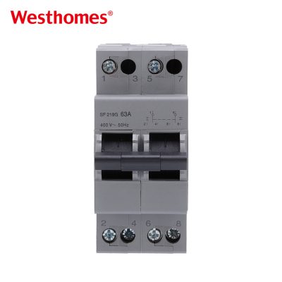
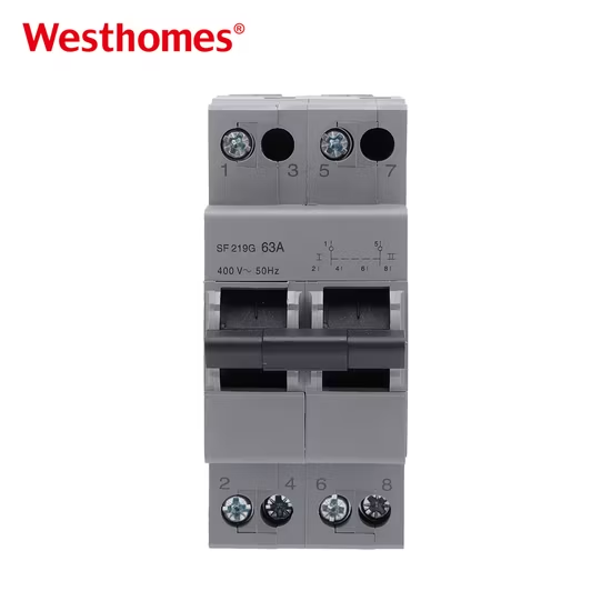
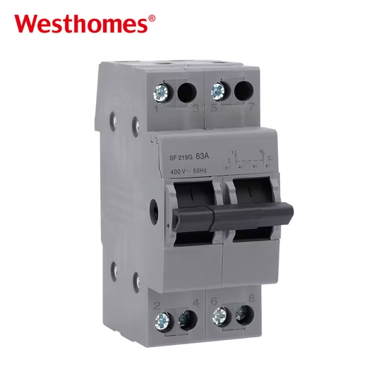
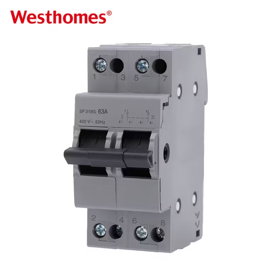
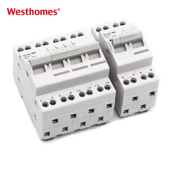
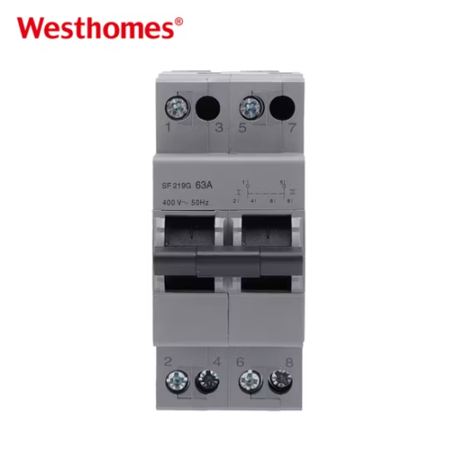
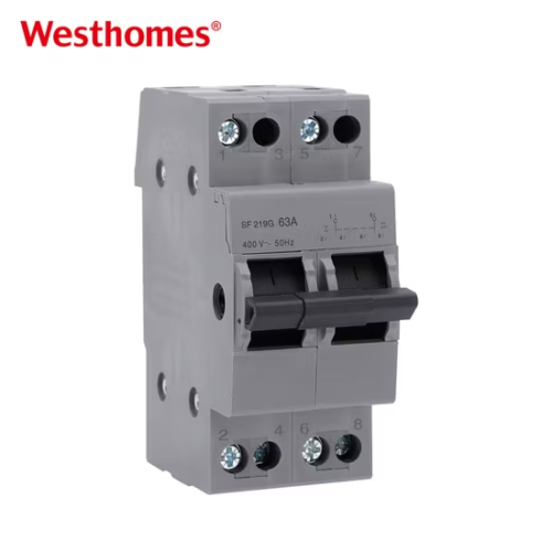
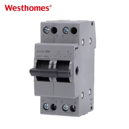
SF219G 2p 63A Dual Power Manual Transfer Switch 230V

Rated for 230V, this SF219G MTS Interlock Isolating Switch ensures that electrical circuits are safely isolated to prevent accidental power cross-over.

Social focus:

SF219G 2p 63A Dual Power Manual Transfer Switch 230V

The 2p 63A Dual Power Manual Transfer Switch is an essential electrical device for homes and industrial applications, designed to seamlessly switch between two power sources while maintaining safety and reliability.
2p 63A Transfer Switch

With its dual power capabilities and manual transfer mechanism, the 2p 63A Dual Power Manual Transfer Switch provides superior control and peace of mind, especially during power outages or maintenance.

This switch is ideal for protecting sensitive equipment and ensuring uninterrupted power supply in residential, commercial, and industrial environments.

KEY INFORMATION

Product Name Dual power manual transfer switch
Item No. SF219G
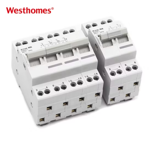
Poles 2P, 4P
Rated Frame Current 63A
Rated Operating Frequency 50/60Hz
Installation Mode 35mm Din rail
Utilization Category AC-22A,AC-21B

Basic Info.

Model NO. SF219G
Certification CCC, CE, ISO9001
Poles 2p, 4p
Voltage AC400V
Rated Frequency 50/60Hz
Transport Package Paper Box
Trademark Westhomes
HS Code 8536200000
Operation Electric
Type Integrated automatic transfer switch
Output type Multiple
Operating Mode Manual
Mounting Type DIN Rail
Specification IEC/EN 60947-6-1
Origin Prc
Production Capacity 15, 000, 000

Packaging & Delivery

Package Size 10.00cm * 10.00cm * 10.00cm
Package Gross Weight 1.000kg

FREQUENTLY ASKED QUESTION (FAQ)

What is a manual dual power transfer switch? plus-square Created with Sketch Beta. minus-square Created with Sketch Beta.

A manual dual power transfer switch is a low-voltage switching device that lets an operator select which of two independent power sources feeds a load circuit. In normal service the load runs from the utility mains (Source I), and during an outage the operator moves the operating handle to connect the load to a backup generator or second feed (Source II). It is the simplest, most reliable way to switch a load between two supplies without wiring both into the same panel.

How is the SF219G different from an automatic transfer switch (ATS)? plus-square Created with Sketch Beta. minus-square Created with Sketch Beta.

An ATS contains voltage-sensing electronics and contactors that detect a mains failure and transfer the load automatically, typically in fractions of a second, and switch back when supply returns. The SF219G is purely mechanical: it has no sensors, no control circuit, and no moving parts that can fail electronically, so it always requires a person to flip the lever. The trade-off is lower cost and greater robustness in remote or harsh locations, against no break-before-make automation.

How do I operate the manual changeover? plus-square Created with Sketch Beta. minus-square Created with Sketch Beta.

With the panel powered, move the rotary/lever handle from the "Mains" position to the "Generator" (or "Backup") position. The internal mechanism breaks the currently connected source first, then makes the second source — a true break-before-make sequence. To return to utility power, restore the mains, then move the handle back. Never force the handle mid-travel; the detent positions define the only three states: Source I on, Source II on, or off.

What does the "2P 63A 230V" rating mean on the SF219G? plus-square Created with Sketch Beta. minus-square Created with Sketch Beta.

"2P" means it switches both line and neutral (two poles) on a single-phase circuit, so it fully isolates the load from either source rather than switching only the hot conductor. "63A" is the maximum continuous current the contacts are designed to carry at 230V AC, 50/60 Hz, without overheating. "230V" is the rated operational voltage, suitable for standard single-phase residential and small commercial supplies.

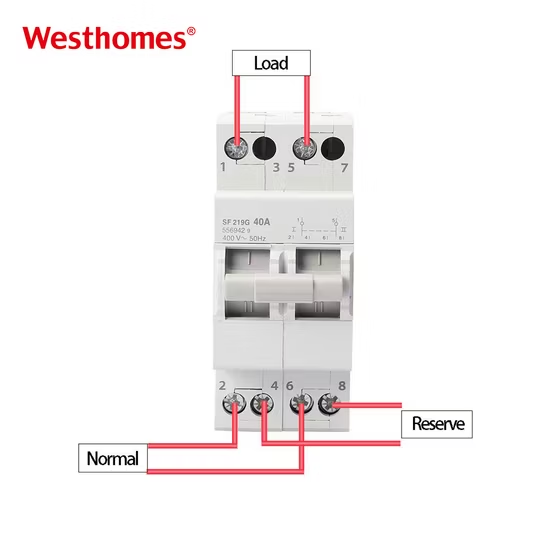
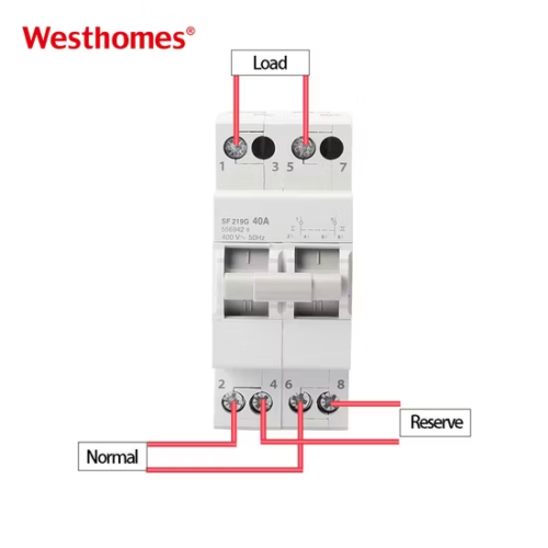
How is the SF219G wired — main source plus generator/backup? plus-square Created with Sketch Beta. minus-square Created with Sketch Beta.

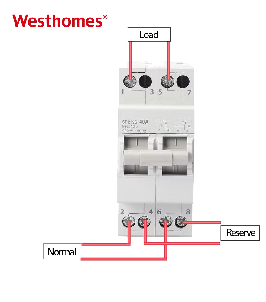
Terminals are typically marked for Source I (mains: L1, N), Source II (generator/backup: L2, N), and a common load output (L, N). Utility line and neutral land on the mains terminals, generator line and neutral on the backup terminals, and the protected load circuits are connected to the common output terminals. The neutral may or may not be switched depending on the internal configuration, so always confirm the wiring diagram on the unit before connecting a generator that has its own neutral arrangement.

What are typical applications for this switch? plus-square Created with Sketch Beta. minus-square Created with Sketch Beta.

It is commonly used for home backup where a portable or standby generator must feed a selected set of circuits, for small shops, farms, telecom shelters, and stand-alone equipment that needs an alternate feed. It is also used as a manual selector between utility and solar/battery inverter in off-grid or grid-tied hybrid systems. The 63A rating suits roughly up to a 14 kW single-phase load at 230V.

Does it have anti-parallel / interlock protection? plus-square Created with Sketch Beta. minus-square Created with Sketch Beta.

Yes. Because the mechanism is mechanically interlocked (break-before-make), the two sources can never be connected to the load at the same time. This prevents paralleling an unsynchronized generator with the utility grid, which would cause catastrophic backfeed, fault currents, and a serious hazard to line workers. The interlock is part of the switch design, not an external add-on.

How is the SF219G installed? plus-square Created with Sketch Beta. minus-square Created with Sketch Beta.

It mounts on a standard 35 mm DIN rail inside a distribution enclosure, or by screw fixing depending on the model. Install it downstream of the main utility breaker and upstream of the branch breakers being backed up. Tighten line, neutral, and load conductors to the torque printed on the label (typically 1.2–2.0 N·m for 63A), keep clearances for both sources, and fit a cover to protect terminals. Qualified electricians should perform the work per local wiring rules.

What maintenance does it require? plus-square Created with Sketch Beta. minus-square Created with Sketch Beta.

There is no routine electrical test like an RCCB, but annually exercise the lever through all three positions several times to keep the contacts clean and the mechanism free-moving. Inspect terminal torque once a year in service, and check for signs of overheating, discoloration, or loose connections. Keep the enclosure dry and free of dust; a switch that has sat in one position for years may develop contact film, so periodic cycling is the main preventative maintenance.

Which international standard does it meet? plus-square Created with Sketch Beta. minus-square Created with Sketch Beta.

Transfer switching equipment of this type is designed and tested to IEC 60947-6-1 ("Low-voltage switchgear and controlgear — Multiple function equipment — Transfer switching equipment"), which defines rated operational current, making/breaking capacity, impulse withstand, and the category of interlock. Mechanical endurance and short-time withstand values are declared by the manufacturer in the datasheet. Compliance with this standard (and relevant national deviations such as CE marking) confirms it is fit as a service transfer switch for low-voltage installations.

RELATED PROJECTS

REQUEST
YOUR FREE QUOTE

* indicates a required field