Get quick appointment for technical support!

SPD Backup Protection: Choosing Between Fuses, Breakers and SCBs
Oct 14, 2026
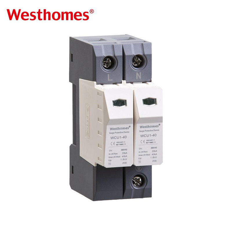
Why an SPD can fail short, and what backup must clear
Metal-oxide varistor SPDs degrade after repeated energy absorption. Heat builds at the varistor, an internal thermal disconnector separates the failed block from the line, and the status window changes. That internal mechanism removes the failed element, but it is not a short-circuit interrupting device. If the varistor welds or takes a line-to-earth fault, the mains still needs an overcurrent device to open.
Spark-gap types add follow current. After the gap fires, supply voltage can keep driving current across it until the gap interrupts, and the manufacturer’s follow-current rating sets what the backup has to tolerate. Ask for evidence covering failure behavior, not just the prominent surge kA on the front label.
Do you always need a separate fuse or breaker?
Adding a dedicated device by habit creates unnecessary complexity; omitting one by habit can leave the documented protection condition unmet. Three arrangements exist:
Existing upstream device
Acceptable only when its operating characteristics satisfy the SPD manufacturer’s requirements and the panel engineering allows that arrangement without compromising supply continuity.
Dedicated branch protection
A separate fuse, circuit breaker, or dedicated surge backup protector installed on the SPD branch, allowing isolated servicing without interrupting main board loads.
Integrated protection
The SPD incorporates an engineered, tested protective function that may remove the requirement for an external backup component within stated application parameters.
Write the chosen arrangement, exact SPD model, protective device type, and document revision into the panel schedule. That makes later component substitutions reviewable instead of restarting the decision process from scratch.
Fuse vs MCB/MCCB vs SCB: what buyers should compare
A resettable button or a large surge number can distract from the protection duty. Compare every option against the same SPD, fault conditions, and maintenance needs before deciding.
| Option | Why you would reach for it | Evidence to request | Main caution |
|---|---|---|---|
| Manufacturer-specified gG/gL fuse | Documented pairing, predictable pulse-energy handling | Exact class, rating, voltage, breaking capacity, coordination table | Same amperage does not mean the same behavior; a generic fuse is not approved |
| MCB or MCCB on the branch | Resettable, familiar, easy service access | Exact family, curve or settings, approved SPD combination | A familiar B/C curve proves nothing about surge coordination |
| Dedicated SCB (surge backup protector) | Built for the SPD duty: rides impulse, clears fault | Surge withstand, fault interruption, exact-model pairing | The SCB label alone does not prove compatibility with your SPD |
| Integrated protection | Shorter component list | Instructions, fault-current limits, protection scope | Internal thermal protection is not full coordination |
There is no universal winner. A blanket claim that every fuse rides surges better than every breaker is not a selection rule. The manufacturer’s coordination table for this exact model decides.
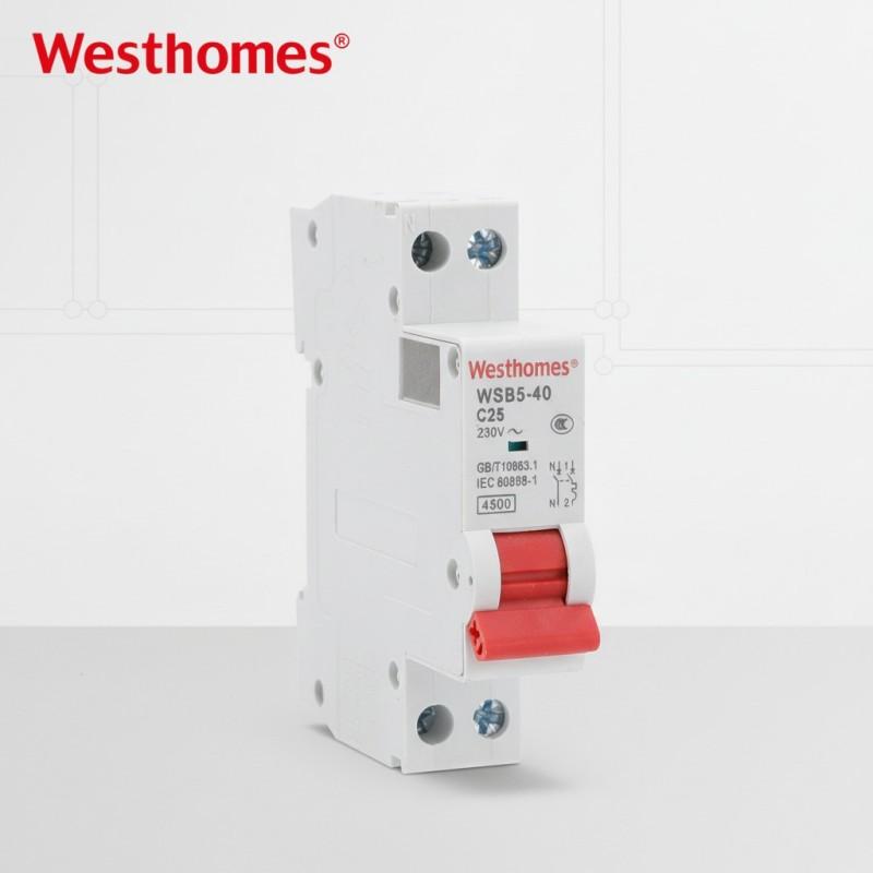
The maximum backup rating is a ceiling, not a default size
Datasheets often print a maximum backup fuse rating. Read that number as a safety ceiling for a stated device type, not the default size to install. A maximum gG fuse rating does not transfer to a circuit breaker of the same amperage because operating trip curves differ substantially. A smaller device is not automatically right either; it must still ride the specified surge impulse and clear the prospective fault current.
When you read a manufacturer table, keep three values separate: the maximum permitted upstream device, the recommended dedicated branch device, and any condition attached to a declared short-circuit rating. They do not mean the same thing in the bill of materials.
Check available fault current on its own
Surge ratings In (nominal discharge current), Imax (maximum discharge current), and Iimp (impulse current, Type 1) describe standardized test impulses. They do not confirm the device can interrupt the available mains short-circuit current at the panel installation point. Calculate the prospective fault current at the SPD location, check the backup device’s interrupting capacity and the SPD’s declared short-circuit withstand, and keep the two parameters in separate evaluation columns.
Waveform travels with the current. Type 1 lightning-current duty uses 10/350 µs; common Type 2 discharge uses 8/20 µs. Never compare a 10/350 µs value against an 8/20 µs value as if they represented the same stress, and keep an impulse peak strictly separate from a power-frequency short-circuit rating.
Layout matters as much as the rating
Connection leads introduce stray inductance, and every centimeter raises the residual let-through voltage the protected equipment actually experiences during a surge. Keep leads short and straight, adhere to manufacturer routing and length thresholds, and do not assume a low clamp voltage on the datasheet compensates for excessive wiring in the enclosure. The panel designer must review conductor routing, equipment insulation withstand, and service access together with component ratings.
What I²t can tell you, and what it cannot
I²t, the current-squared-time integral expressed in A²s, quantifies thermal pulse energy stress. For fuses, melting I²t differs from total clearing I²t, which includes the arcing phase until final circuit interruption. Pulse shape, ambient temperature, pre-loading, and repeated impulses all alter the empirical result. Use I²t data to frame precise technical questions for the manufacturer, not to size a universal fuse, and never approve a circuit breaker based on a fuse-style melting calculation.
What to put in the SPD backup RFQ
An RFQ that asks only for an SPD and a matching breaker leaves suppliers guessing. Send a comprehensive project data sheet and request documented evidence on the complete proposed arrangement:
Electrical supply parameters
AC or DC system, nominal voltage, frequency, earthing system (TN, TT, IT), and line configuration.
Exact component identification
Complete SPD catalog model number, suffix designations, and official datasheet revision level.
Declared impulse ratings
Specified surge parameters including In, Imax, Iimp, and maximum continuous operating voltage (Uc).
Prospective fault current
Verified available short-circuit current calculated at the specific panel bus location.
Upstream protection data
Characteristics, rated breaking capacity, and trip curve settings of the existing upstream device.
Enclosure layout constraints
Conductor cross-sections, total connecting lead length limits, and ambient thermal operating limits.
Compliance & accessories
Required regional certifications, visual status indicators, remote signaling auxiliary contacts, and quantities.
Ask the supplier to name the proposed backup device, provide the official coordination report, and specify any operational limits. Confirm surge impulse withstand and mains fault interruption independently, and state what changes if a component substitution is made later.
Frequently asked questions
Can the main breaker serve as SPD backup protection?
Only if the SPD instructions allow that arrangement and the device characteristics, available fault current, and conditions meet the stated requirements. A separate branch device may be preferred for maintenance access and supply continuity. Check the exact combination rather than assuming either arrangement is always required.
Can I size the backup MCB from Imax alone?
No. Imax describes a surge-current duty, not the complete backup requirement. Check the manufacturer’s approved device, relevant waveform, operating voltage, available fault current, and coordination conditions. A current rating or trip-curve label does not prove suitability.
Is an SCB always better than a fuse or circuit breaker?
No. It is another option, judged against documented performance for this exact SPD and application. The SCB label does not establish universal compatibility, fault interruption, selectivity, or market approval.
Does the internal thermal disconnector replace external backup protection?
Not automatically. Thermal disconnection and short-circuit protection serve different duties. Follow the SPD’s complete installation instructions; some integrated designs permit use without an external device within stated limits.
Can an AC SCB protect a PV DC SPD?
Only if its documentation supports the required DC voltage, fault-interruption duty, and SPD pairing. An AC rating does not establish PV DC suitability. Use application-specific devices and coordination evidence on the DC side.
Closing
An undocumented pairing leaves the protection decision half-made. Do not choose by amperage or surge kA. Confirm the exact combination, fault-current capability, and installed layout, then keep that evidence through purchasing and maintenance.
Ready to specify the backup?
Send us the exact SPD model, supply details, available fault current, and upstream arrangement, and we will return the matching backup option, coordination evidence, and a line-by-line quote.
Keep reading
Standards referenced (verify current editions for the project)

--- END ---