Get quick appointment for technical support!

AFDD Selection Guide: 7 Checks Before You Buy
Oct 29, 2026
Why a current rating isn’t a specification
Most AFDD inquiries start the same way: “Please quote a 16 A AFDD.” That message leaves too much open. The supplier can return with a device matching the ampere rating that still fails approval later because the certificate covers a different variant, the package omits residual-current protection, the trip curve is wrong for the load, or the module simply does not fit the distribution board.
An AFDD monitors the current waveform for hazardous arc signatures: the kind that originate at a loose terminal, a cracked conductor, or compromised insulation, heating up long before anyone notices. A conventional MCB trips on overcurrent, while an RCD trips on earth leakage. A series arc often continues drawing roughly normal current and remains balanced on neutral, leaving both conventional devices blind. That critical blind spot is exactly what the AFDD addresses.
This guide is for buyers, distributors, and panel builders comparing AC DIN-rail AFDDs for IEC-based projects. Circuit design and installation must always remain the responsibility of a qualified professional.
The current rating alone reveals nothing about standards, architecture, curve, breaking capacity, RCD type, or board fit.
IEC 62606 AFDD and UL 1699 AFCI are distinct products engineered for different markets; they are not interchangeable.
AFDD+MCB, AFDD+RCBO, and standalone AFD units are three fundamentally different packages. Resolve this before comparing prices.
The B/C curve governs overcurrent tripping, not arc sensitivity. Increasing the rating to silence nuisance trips does not work and risks underprotecting the cable.
| Device | What It Detects | What It Does Not Replace |
|---|---|---|
| MCB | Overload and short-circuit overcurrent | Residual-current or arc-pattern detection |
| RCD / RCCB | Residual-current imbalance to earth | Overcurrent protection |
| RCBO | Overload, short-circuit, and residual current | Arc detection, unless explicitly designated as an AFDD-RCBO |
| AFDD | Defined hazardous arc signatures, both series and parallel | Overcurrent, residual-current, or surge protection |
| SPD | Transient overvoltage | Overcurrent, residual-current, or arc protection |
The AFDD sits alongside the rest of the protection scheme. It never replaces correct wiring, overcurrent protection, or earthing. If you need to understand the detection principle before diving into selection details, our arc fault protection guide explains how the device analyzes current waveforms and executes tripping.
Match the product standard to the destination market first
A brochure naming a standard is not proof that the offered model is certified to it. Start here, because a regional compliance mismatch cannot be rectified by commercial negotiation after the order is placed.
Keep two fundamental questions distinct. The product standard governs how the device is manufactured and tested. For household and similar AC installations, that standard is IEC 62606, along with regional adoptions like BS EN 62606. Conversely, the installation code and local wiring regulations instruct the electrical designer where arc-fault mitigation is mandated or recommended (e.g., national editions based on IEC 60364-4-42). Simply stating “it is an IEC country” does not establish compliance. Record the exact destination country, code edition, building occupancy classification, and circuit type.
Furthermore, never confuse an AFDD with an AFCI. In the United States and Canada, the equivalent protective device is an AFCI, evaluated under UL 1699 in the US and CSA C22.2 No. 270 in Canada. System voltages, enclosure listing criteria, neutral switching rules, and test protocols differ significantly. A CE-marked IEC AFDD is not automatically approved for North American loadcenters, and the reverse applies equally.
Request the complete technical submission upfront: model designation, datasheet, instruction manual, schematic wiring diagram, time-current curves, declaration of conformity, and accredited third-party test certificates (CB Scheme or equivalent). On the test certificate, cross-reference the issuing body, exact model number, certified ampere ratings, and standard revision against the formal quotation. A certificate issued for a sibling variant does not cover your model. Notably, the CE mark represents the manufacturer’s own declaration of conformity, not an independent laboratory certification.
If a vendor supplies only marketing collateral and cannot furnish a test certificate explicitly stating the requested model and rating, place the procurement on hold.
Decide the protection architecture before comparing models
Two devices both marketed under the term “AFDD” can deliver vastly different functional scopes. Lock in the electrical architecture first; otherwise, you will be comparing unit pricing across incompatible product categories.
| Architecture | Functions Included | What to Check |
|---|---|---|
| Standalone AFD unit with opening means | Arc detection and tripping mechanism | Which declared MCB/RCD pairs with it; obtain the evaluated and certified combination |
| AFDD + MCB | Arc fault, overload, and short-circuit protection | Where independent residual-current protection is still required in the scheme |
| AFDD + RCBO | Arc fault, overload, short-circuit, and residual-current protection | RCD type, sensitivity (IΔn), curve, and poles, verified individually |
A shared upstream RCCB versus dedicated individual AFDD-RCBOs is the classic engineering trade-off. An upstream RCCB feeding multiple AFDD+MCB sub-circuits reduces initial hardware costs. However, a single earth-leakage event disconnects all downstream circuits, cumulative electronic leakage can cause nuisance trips, and troubleshooting becomes difficult. Conversely, an integrated AFDD+RCBO isolates residual-current faults strictly to the affected circuit, guarantees service continuity across unaffected zones, and simplifies fault tracing—albeit requiring more panelboard module real estate and individual circuit allocation. The project designer establishes the layout; the procurement team must ensure the quote matches the specification.
When selecting a standalone AFD unit, obtain the manufacturer’s officially declared protective-device pairing table and assembly guidelines. Adjacent modular devices sharing DIN rail space have not necessarily undergone coupled fault-interruption testing; visual similarity is never evidence of coordinated performance.
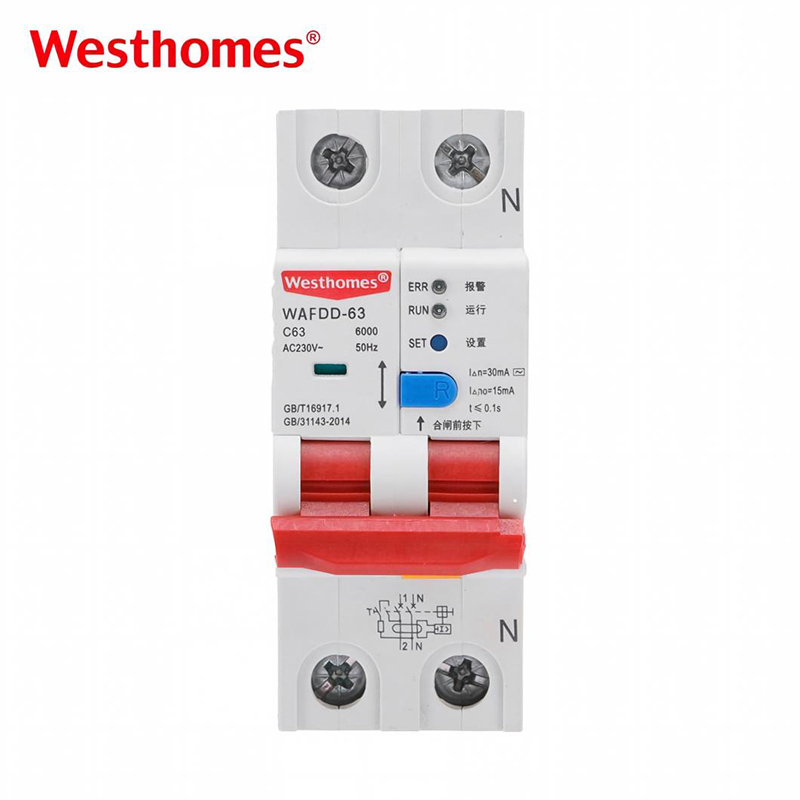
Westhomes adopts the fully integrated approach: the WAFDD-63 unites arc fault detection with residual-current, thermal overload, and instantaneous short-circuit protection in a compact housing. Available from 6 A to 63 A across B, C, and D trip characteristics with 6 kA breaking capacity and optional over/undervoltage protection. Send your circuit details if you want us to check whether it fits your board.
Freeze every electrical rating on its own line
A broad description such as “32 A AFDD” leaves breaking capacity, trip curve, and RCD performance undefined. Assign every critical parameter to an independent specification column and require formal approval from the electrical engineer.
Voltage and Frequency: Define nominal operational voltage, permitted operational range, and AC frequency separately. A 230 V / 50 Hz device cannot be presumed operable on a 120 V / 60 Hz network, as internal arc-sensing microcontrollers require stable auxiliary supply across the full line spectrum.
Rated Current (In): Coordinate rated current precisely between calculated design current and corrected conductor ampacity:
Here, Ib represents the design load current, In is the nominal device rating, and Iz is the continuous current-carrying capacity of the cable after applying derating factors for ambient temperature, cable bunching, routing conduits, and thermal insulation. Never determine In from appliance nameplates alone, and never jump from 16 A to 25 A to bypass recurring trips. An unexplained arc trip cannot be resolved by upsizing the breaker, which leaves building wiring dangerously underprotected.
Overcurrent Trip Curve (B / C): The instantaneous magnetic trip threshold is governed by the curve. Curve C tolerates standard motor and inductive inrush currents, whereas Curve B trips faster at lower thresholds for sensitive domestic circuits. Select the curve based on load inrush profiles and earth fault loop impedance calculations. The curve has no relation to arc-fault detection sensitivity; substituting Curve B with Curve C will not prevent an arc-detection trip.
Short-Circuit Breaking Capacity: Match the rated short-circuit capacity (e.g., Icn per IEC 60898-1) against the prospective short-circuit current (PSCC) calculated at the installation busbar. A 6 kA breaker is prohibited in an 8 kA fault location unless supported by a certified, tested upstream backup coordination scheme. The terms Icn, Icu, and Ics denote different test sequences and are not interchangeable.
RCD Type and Sensitivity (AFDD+RCBO): Specify both characteristics explicitly. IΔn (rated residual operating current): 30 mA is standard for personal protection, but verify local code mandates. RCD Operating Class: Type AC detects sinusoidal AC residual currents, while Type A detects both sinusoidal AC and rectified pulsating DC components commonly generated by EV chargers, induction hobs, and variable-speed drives. Complex power electronics may mandate Type F or Type B. Integrating arc detection does not eliminate the necessity of selecting the correct RCD class.
A supplier offer that matches continuous current and breaking capacity but provides an incorrect curve or states “30 mA” without confirming Type A or AC is a technical deviation, not a compliant quotation.
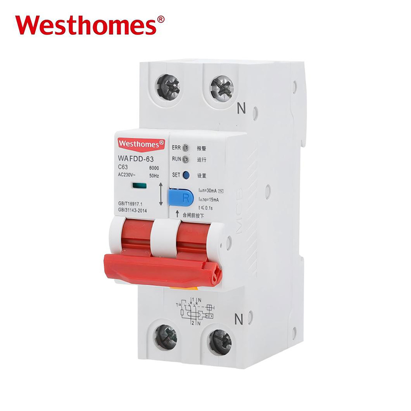
Check poles, neutral routing, and feed direction
The ampere rating provides no information regarding conductor compatibility. Review the single-line diagram directly alongside the manufacturer’s terminal connection schematic.
When evaluating 1P+N versus 2P configurations, determine which poles feature switched contacts, which carry active thermal-magnetic trip elements, and whether true electrical isolation is guaranteed across all conductors. Most line-to-neutral AFDDs require dedicated line and neutral connections; verify whether the neutral is switched or unswitched and ensure it complies with local installation codes. For multi-wire branch circuits or shared neutrals, deploy only devices specifically evaluated for those topologies. Never split conductors across unlinked single-pole devices lacking common-trip certification.
Line and load terminal orientation is equally vital. Verify whether the device requires top-feed or bottom-feed before releasing panelboard fabrication drawings. Reversing supply and load connections can disable the internal sensing electronics or cause immediate tripping upon power application.
If a supplier’s proposal omits wiring diagrams or the neutral configuration conflicts with the facility’s earthing system, clarify the design before placing orders.
Verify board, busbar, and thermal fit, not just the rail
A device can latch onto a standard 35 mm DIN rail and still fail installation: terminal cages may misalign with the comb busbar, the modular width may exceed panel space, or thermal dissipation can overheat an enclosed distribution board.
Examine the physical interface comprehensively: overall modular width (AFDDs frequently require more than one standard 18 mm DIN module, meaning retrofitting a single-module RCBO might require a larger enclosure), busbar profile (pin-type or fork/tongue-type), comb pitch, phase alignment, and verified busbar part numbers. Confirm terminal specifications: allowed conductor metallurgy (copper/aluminum), permissible wire cross-sections (mm² / AWG), multiple-conductor clamping allowances, strip length requirements, ferrule mandates, and screw tightening torque. Assess enclosure depth, rail-to-door clearance, and space for incoming flying leads.
Thermal management demands identical rigor. Request internal watt-loss ratings, maximum ambient operating temperatures, and assembly derating tables for panel builders. A distribution board loaded with multiple electronic arc-fault breakers runs substantially hotter than an isolated breaker in an open test rig, meaning nominal ratings must be derated to maintain reliability.
Cross-brand integration requires certified validation. Installing an AFDD from one manufacturer onto another brand’s proprietary busbar or retrofitting new modules into legacy enclosures mandates compliance verification under the IEC 61439 switchgear assembly standards. Clean rail mounting and identical exterior plastic colors do not constitute tested compatibility. If a vendor cannot supply mechanical dimension drawings, torque specifications, or busbar profiles and recommends a substitute solely because “it looks identical,” pause the purchase.
Read the manual for testing, self-monitoring, and trip indication
Inspect the operation manual before approving procurement, not during site commissioning. Maintenance technicians must know how to execute routine testing and interpret fault trip records.
Regarding the manual test button (T button) and automatic self-monitoring, establish: the frequency of internal self-tests, the visual indication of internal sensor failure, the operational voltage required for test-button activation, and the testing procedure for verifying both AFDD and RCD functions on combination units. Verify the manufacturer’s protocol for handling internal microprocessor self-test faults.
For fault diagnosis, verify the status indication matrix: does the unit clearly differentiate between an arc fault, residual-current trip, thermal overload, overtemperature, or internal hardware error? Are series and parallel arcs indicated with distinctive LED flash patterns? While some breakers utilize mechanical trip flags, others rely on LED sequences visible only during initial re-energization. Technicians must document the fault sequence before cycling the toggle, as resetting can erase volatile diagnostic memory.
Obtain the approved insulation-resistance test protocol. Standard 500 V DC or 1,000 V DC high-voltage megger testing can permanently destroy sensitive arc-sensing circuitry unless specific disconnection procedures are followed. Never attempt to verify an AFDD by intentionally creating open sparks, cutting cable insulation, or loosening screw terminals; this is dangerous, invalid, and fails to replicate standardized IEC 62606 waveform parameters.
An installation manual that lacks a comprehensive diagnostic chart, self-test overview, or insulation test precautions represents an incomplete technical deliverable.
Send a complete, identical RFQ package to every supplier
A lower bid frequently conceals missing certifications, omitted protective functions, or inferior components. Issue an identical, itemized technical schedule to every manufacturer, and enforce a mandatory deviation list with every submission to ensure objective technical assessment before commercial negotiations.
| RFQ Field | What to Provide |
|---|---|
| Market and evidence | Destination country, applicable wiring code editions, and required certificates / test reports |
| Architecture | Standalone unit, AFDD+MCB, or AFDD+RCBO; declared equipment pairings where applicable |
| System parameters | AC voltage and range, frequency, phase arrangement, earthing topology, poles, and neutral handling |
| Circuit ratings | Rated current (In) and B/C curve per circuit, load characteristics, and PSCC breaking capacity |
| Residual current | IΔn sensitivity (e.g., 30 mA), RCD class (Type A / AC), and upstream selectivity requirements |
| Assembly interface | Board and busbar specifications, layout drawings, module width limits, and enclosure thermal data |
| Testing and diagnostics | Self-test behavior, manual T-button protocol, trip status flags, and insulation-testing procedures |
| Commercial terms | Quantities per model, delivery milestones, sample requirements, custom labeling, MOQ, and lead times |
Require that bulk deliveries strictly match approved sample configurations, establishing in writing that any component change mandates a fresh technical submission. If a vendor returns pricing solely for a “16 A AFDD” without datasheets or compliance statements, that quotation cannot be considered a valid, comparable bid.
A quick worked example (hypothetical, for illustration)
Consider a 230 V / 50 Hz single-phase hotel guestroom socket circuit: assessed continuous load of 3.0 kW at PF 0.95, giving a design current Ib ≈ 13.7 A; corrected conductor current-carrying capacity Iz = 18.7 A; prospective short-circuit current at the panelboard is 3.4 kA; local wiring regulations mandate 30 mA personal residual-current protection, and the fire risk assessment requires arc-fault mitigation in sleeping accommodation.
1
2
3
4
5
6
7
This process qualifies a compliant 16 A candidate. The project electrical engineer still calculates voltage drop, loop impedance disconnection times, and harmonic distortion profiles before finalizing approval.
Frequently asked questions
Only a device explicitly certified and marked as an integrated AFDD-RCBO provides arc, overload, short-circuit, and residual-current functions in one unit. A standalone AFDD or AFDD+MCB does not replace residual-current protection. Always check the markings, certificate scope, and datasheet.
Coordinate In with design current, corrected conductor capacity, installation method, ambient temperature, grouping, and the integrated overcurrent characteristic. Do not select from the appliance nameplate alone, and never raise the rating to mask unexplained trips.
There is no universal worldwide rule. Requirements depend on the adopted installation standard and edition, building use, circuit purpose and rating, national amendments, insurer requirements, and project risk assessment. Confirm the exact jurisdiction before building the BOM.
AFDD follows IEC 62606 for IEC-style installations; AFCI follows UL 1699 / CSA C22.2 No. 270 for North America. Both address the arc hazard but are not interchangeable products across different markets.
Generally, no. AFDDs sit at the origin of the final circuit they protect, and individual devices improve fault location and service continuity. Any shared arrangement must be permitted by the applicable standard and the manufacturer’s instructions.
The AFDD detects hazardous high-frequency arc signatures rather than gross overcurrent or earth-leakage imbalance. A series arc can draw normal operating current, and a line-to-neutral parallel arc remains balanced from the RCD’s perspective. Inspect the trip diagnostic display before resetting; an integrated unit may have operated on another protective function.
Closing
An AFDD procurement package is complete only when four pillars are defined: the circuit application, regional compliance standards, protection architecture and ratings, and the physical panelboard interface. If an inquiry states merely “AFDD, 16 A,” the manufacturer lacks the technical data required to specify the correct unit.
Follow these seven verification steps, attach installation single-line diagrams, and demand certified documentation accompanied by a written deviation log with every bid. This disciplined approach eliminates rejected consignments, unexplained price variations, and hazardous on-site substitutions.
Send our engineering team your project destination country, operating voltage, frequency, nominal current ratings, required integration package (AFDD+MCB or AFDD+RCBO), pole configuration, short-circuit levels, residual-current criteria, panelboard drawings, required quantities, and certification mandates. We will respond with an exact model recommendation, full technical datasheets, and an itemized line-by-line quotation detailing any deviations.
When Arc Faults Happen and How Protection Works
IEC 62606
IEC 60364-4-42
UL 1699 / CSA C22.2 No. 270
BS EN IEC 61439
National Regulations

--- END ---
Related Products