Get quick appointment for technical support!

Reversing Motor Control and Interlocking
Sep 27, 2026
A reversing starter is two contactors arranged so that the motor can turn either way. The wiring is only slightly more involved than a single direction starter, and the consequences of getting it wrong are not. A reversing starter that closes both contactors at once puts a short circuit across the supply through two sets of contacts.
This guide takes four failures that appear on reversing starters and works through what causes each, how it shows up, and what stops it.
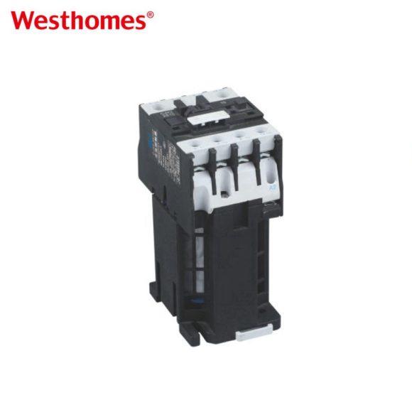
What Reversing Demands That Starting Does Not
Two contactors feeding one motor are connected so that one reverses two of the three phases. That arrangement means the output of one contactor is a short circuit across the output of the other, and the only thing preventing it is that they are never closed together.
| Failure | How it shows up | What prevents it |
| Both contactors close together | A bang and two destroyed contactors | Electrical interlock backed by a mechanical one |
| Interlock wired but never tested | Drawing looks right, protection absent | Continuity test with the supply isolated |
| Reversal before the shaft stops | A current spike above the starting current | Delay the direction change until the shaft stops |
| Relay set for one direction only | Trips one way and holds the other | Set from the higher of the two running currents |
The requirement is therefore not about the motor at all. It is about guaranteeing that exactly one of the two is closed at any moment, and that guarantee has to survive a stuck button, a welded contact and a person holding both.
Failure One, Both Contactors Close Together
The symptom is a loud bang and two destroyed contactors, often with a tripped device upstream. The cause is either a missing electrical interlock or a welded auxiliary contact that made the interlock ineffective.
The electrical interlock puts the normally closed auxiliary contact of one contactor in the coil circuit of the other. If that contact welds closed, the interlock no longer exists and the second contactor can energize while the first is still closed. The failure is invisible until the moment it counts.
The mechanical interlock is the backstop. It is a physical block between the two contactors that prevents both armatures being closed at once, and it works even when the electrical interlock has failed. A reversing starter with only an electrical interlock is relying on a single small contact.
Failure Two, the Interlock Is Wired but Never Tested
The symptom is an interlock that appears correct on the drawing and does nothing in service. The cause is usually a wiring error in the auxiliary contact that is not visible without testing, such as the wrong contact used or a link left in place.
Testing is done with the supply isolated and a meter across the coil of the contactor that should be prevented. Pressing the opposite button should show no continuity to the coil. A continuity reading where none should exist is the error, and it takes a minute to find.
The check belongs at commissioning and again after any work on the control circuit. Control wiring is modified more often than power wiring, and each modification is a chance to lose the interlock.
Failure Three, Reversal Before the Shaft Stops
The symptom is a current spike far above the starting current, and contact wear that is much faster than the duty suggests. The cause is a direction change commanded while the motor is still turning, so the starter is closing into a rotating load.
The motor is acting as a generator while it coasts, and closing the opposite contactor connects two voltages that are out of phase. The resulting current is larger than a direct start, and the mechanical load on the shaft is reversed as well.
The published mechanical life for the contactor range drops as the duty becomes heavier, and reversing duty sits at the heavy end. A frame selected on the running current alone will have a shorter life than the same frame on a non-reversing duty.
Failure Four, the Relay Is Set for One Direction
The symptom is a relay that trips in one direction and holds in the other. The cause is a setting made with the motor running one way, where the current differs slightly between directions because of the load.
A reversing application drives something that has a preferred direction, such as a conveyor that is loaded one way. The current in each direction is then different, and a single setting has to cover both.
The setting is taken from the higher of the two running currents rather than from the nameplate. Where the difference is large enough to change the setting, the load rather than the relay is the thing to look at.
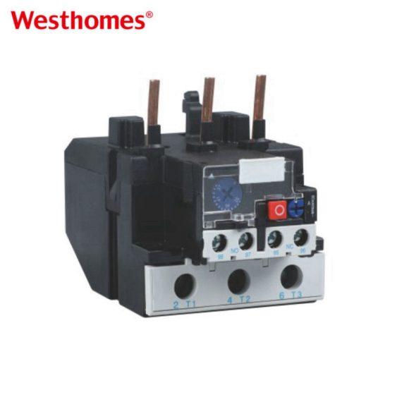
Testing a Reversing Starter Before It Runs
- Confirm the two contactors are mechanically interlocked as well as electrically interlocked.
- With the supply isolated, confirm the interlock prevents the opposite coil energizing.
- Confirm the forward and reverse buttons cannot both be latched at once.
- Confirm any direction change is delayed until the motor has stopped or nearly stopped.
- Record the running current in each direction and set the relay from the higher figure.
- Check the auxiliary contacts for welding at every service, not only at commissioning.
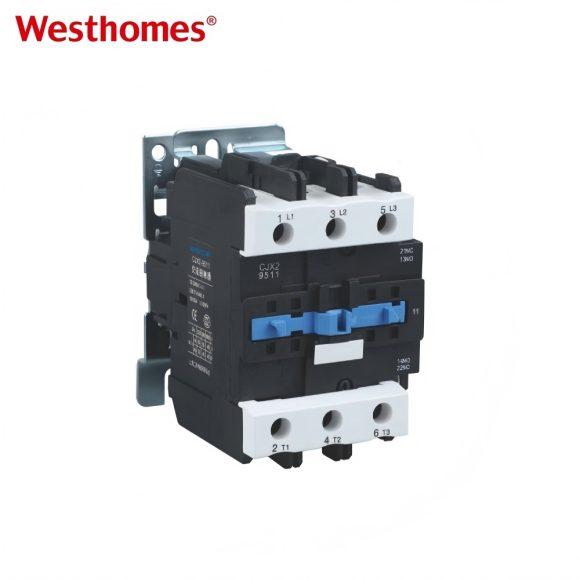
The relay selection and the setting method are covered in the guide on setting a thermal overload relay, and the contactor frames used for reversing duty are listed under CJX2 series AC contactor.
The Drawing You Should Have Before You Start
A reversing starter is one of those circuits where the drawing is worth more than the wiring time. Draw the two coils, the two interlocks and the two buttons before touching a terminal, and mark which auxiliary contact is normally closed.
Most of the failures above are visible on a drawing and invisible in a panel. A mechanical interlock that is not on the drawing does not get fitted, and a normally closed contact that is drawn as normally open gets wired as normally open.
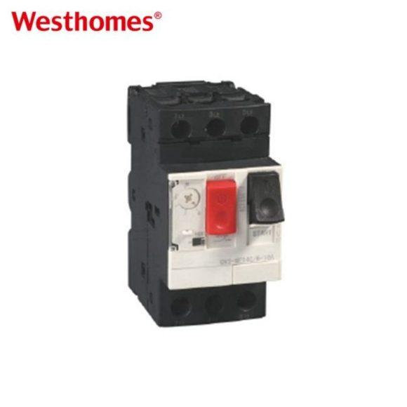
The device that protects the motor regardless of direction is covered in the comparison under motor protector, which sets out where that device belongs relative to a relay.
What This Comes Down To
Reversing control adds one requirement to a standard starter, and that requirement is that the two contactors are never closed together. It is met by an electrical interlock, backed up by a mechanical one, and confirmed by a test that takes a minute. The other three failures here come from the load rather than from the wiring, and each shows up as a current that does not match the calculation. Draw the circuit, test the interlock, and set the relay from the higher of the two directions.

--- END ---
Prev: WSB1-63 Miniature Circuit Breaker
Already the latest article
In this blog
Featured Articles
Get A Free Quote
