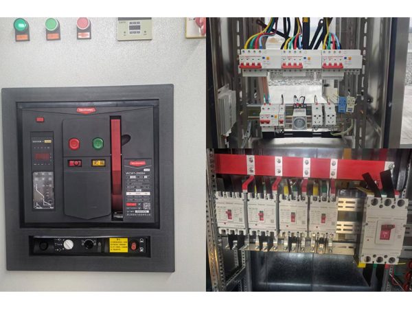
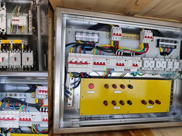
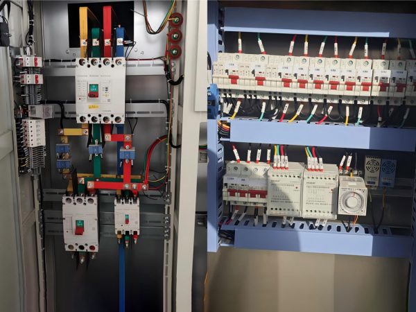
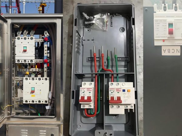
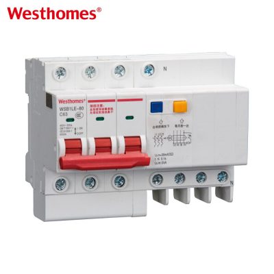
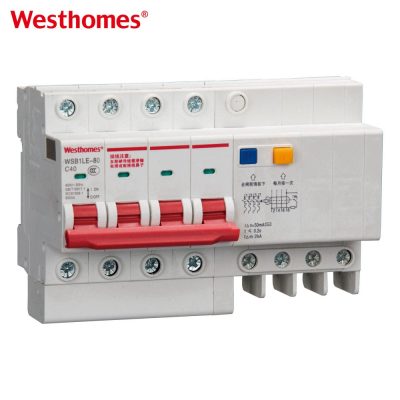
WSB9SZ-125 Moulded case circuit breaker
WSBSZ9-125 is one of updated type MCCBs researched and developed by the company by using advanced design and manufacture technology internationally.
Get quick appointment for technical support!

WSB9-125 series MCB is one of updated type MCCBs researched and developed by the company by using advanced design and manufacture technology internationally.

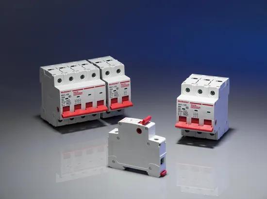
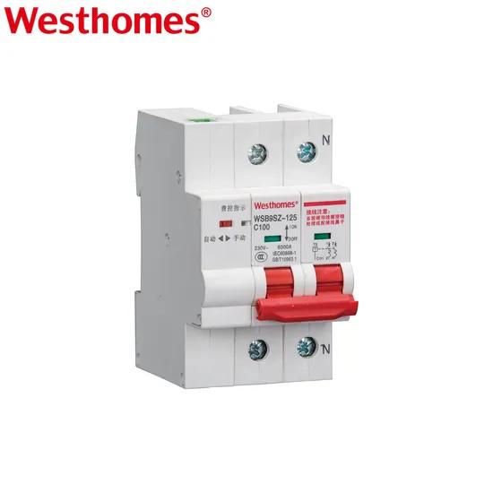
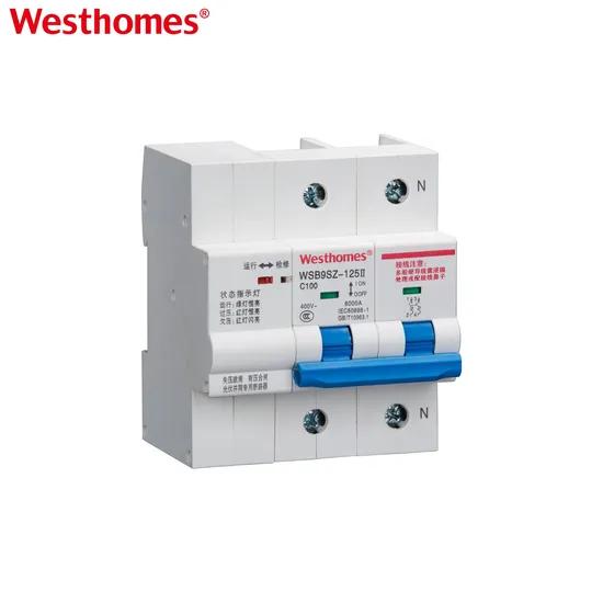
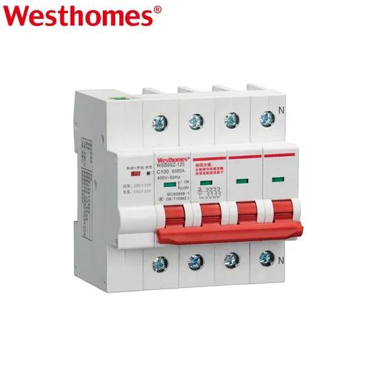
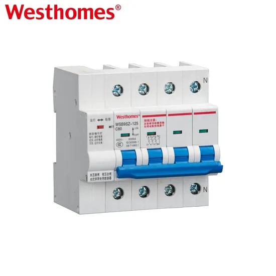
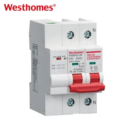
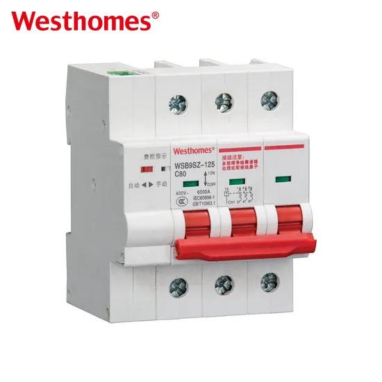
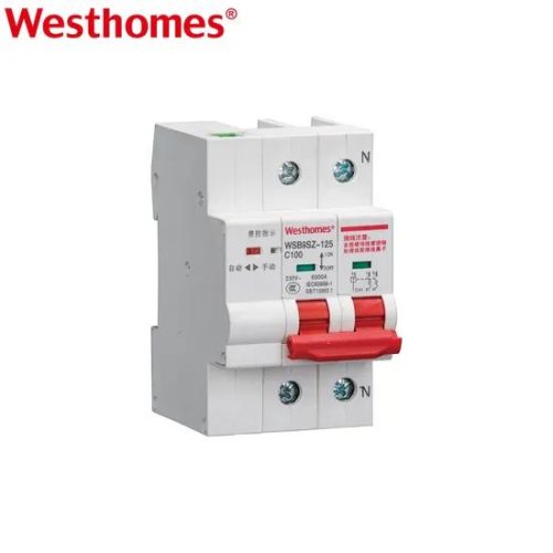
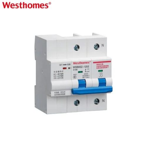
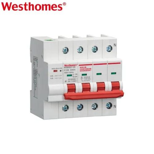
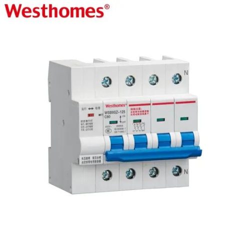
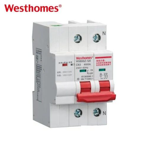
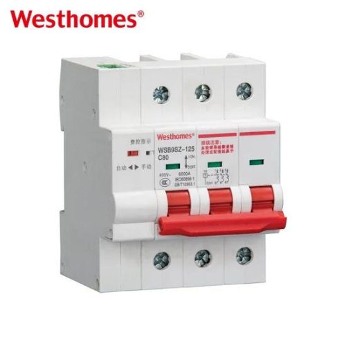
WSBSZ9-125 is one of updated type MCCBs researched and developed by the company by using advanced design and manufacture technology internationally.
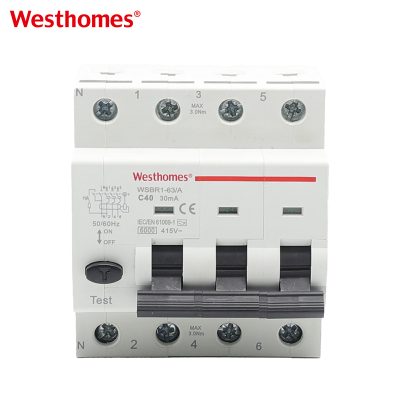
WSB9 series Miniature circuit breakers (hereinafter referred to as circuit breakers) are suitable for AC 50Hz or 60Hz, rated working voltage AC230V/400V, rated current up to 80A lines, for overload and short circuit protection of the lines, and can also be used for infrequent operation conversion of the lines. The circuit breaker is suitable for commercial office buildings, residential buildings and similar buildings. This product complies with GB10963.1 and IEC60898-1 standards.
| Pole | 1P+N; 3P+N |
| Voltage | AC230V/400V |
| kA | 6kA |
| Amps | 6, 10, 16, 20, 25, 32,40, 50, 63, 80, 100, 125 |
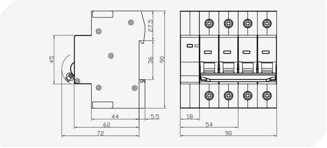
| Width | 54, 90mm |
| S.No | Test current (A) | Initial state | Time limit | Current rating (A) | Expected result | Environment temperature | remarks |
| 1 | 1.13In | Cold | t≤1h | In≤63 | Not tripping | 30ºC~35ºC | |
| t≤2h | In>63 | ||||||
| 2 | 1.45In | Just follow the last test item | t<1h | In≤63 | Tripping | 30ºC~35ºC | Current rises to the set value in 5s steadily |
| t<2h | In>63 | ||||||
| 3 | 2.55In | Cold | 1s | In≤32 | Tripping | 30ºC~35ºC | |
| 1s | In>32 | ||||||
| 4 | 5In | Cold | t≤0.1s | Not tripping | 30ºC~35ºC | Connect the current by closed auxiliary switch | |
| 10In | t<0.1s | Tripping | |||||
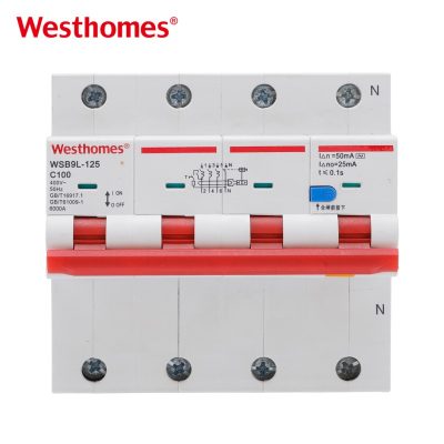
3P+N means the breaker has three overcurrent-protected poles (L1, L2, L3) plus a neutral pole. The three phase poles carry thermal and magnetic protection, while the neutral pole usually opens together with (or after) the phases and provides no overcurrent trip. This is the standard configuration for 400 V three-phase four-wire distribution to commercial and industrial loads.
Feed L1, L2, L3 and the incoming neutral into the four line-side terminals marked on the body, and run the corresponding L1, L2, L3 and neutral out to the load on the load side. Maintain line-in/load-out orientation; reversing the mains can misalign the arc chute and wiring safety interlocks. Use ferruled lugs or appropriately sized copper conductors tightened to the listed torque.
Each of the three phase poles contains a bimetal for time-delay overload and a solenoid for instantaneous short-circuit trips. The neutral pole is a mechanical contact that opens simultaneously but has no trip element of its own, because neutral conductors are not normally fused to prevent loss of neutral while phases remain live.
Curve C (5–10 × In) is the default for general commercial and mixed-resistive/inductive loads such as offices, lighting, and distribution boards. Choose Curve D (10–20 × In) for motor-starting or transformer inrush that would nuisance-trip a C curve, and Curve B (3–5 × In) only for purely resistive, low-inrush final circuits.
Calculate Ib = P / (√3 × U × cos φ) for the balanced load, then choose In so that Ib ≤ In ≤ Iz, where Iz is the ampacity of the phase conductors. The neutral conductor is sized according to harmonic load rules (often 100% if triplen harmonics are significant), but its rating is not the MCB's phase rating.
The series is rated for a standard industrial short-circuit breaking capacity (typically 6 kA to 10 kA depending on the specific frame), declared on the nameplate. In a building fed by a large transformer or very low-impedance supply, the prospective short-circuit current can exceed this, so the panel's available fault current must be calculated and upstream backup coordination selected.
Its 3P+N configuration and up-to-100A frame make it best suited to commercial, light-industrial, and three-phase residential incomer or sub-main applications. Single-phase household final circuits are normally served by 1P or 1P+N breakers, but a 3P+N breaker is a sensible main protective device for a three-phase-fed home or workshop.
As a low-voltage AC miniature circuit breaker in the 6–100A range, it is designed and manufactured to IEC 60898-1 (or the equivalent product family standard for moulded-case mini breakers) and carries CE marking. The nameplate should show the rated voltage, In, Ue, breaking capacity Icn/Icu, and the applicable standards.
This is classic nuisance tripping from inrush current. A direct-on-line motor can draw 5–7 × full-load current for a fraction of a second, which lands inside the C-curve magnetic band. Either move to a D-curve unit, reduce start-up current (soft starter or star-delta), or confirm the cable and load sizing before assuming the breaker is defective.
Every 1–2 years, with power isolated and lockout applied, check that all four terminals are torqued to specification, inspect the enclosure and contacts for discoloration, and manually cycle the on/off handle several times to free the mechanism. After any interruption of a significant short-circuit, replace the breaker rather than reusing it, because internal contacts and the arc chute may be damaged even if the unit still switches.
* indicates a required field

 2 MB
2 MB