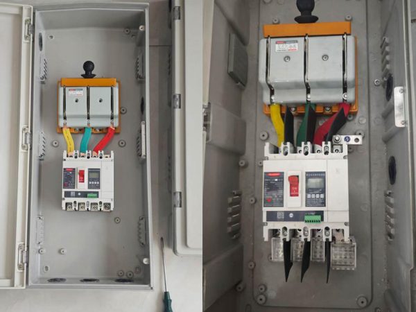
WCU8 Moulded case circuit breaker
WCU8 is one of updated type MCCBs researched and developed by the company by using advanced design and manufacture technology internationally.
Get quick appointment for technical support!

WCU8 is one of updated type MCCBs researched and developed by the company by using advanced design and manufacture technology internationally.



WCU8 is one of updated type MCCBs researched and developed by the company by using advanced design and manufacture technology internationally.
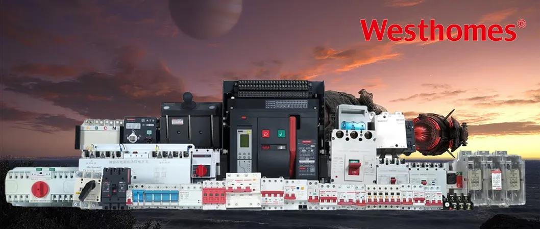
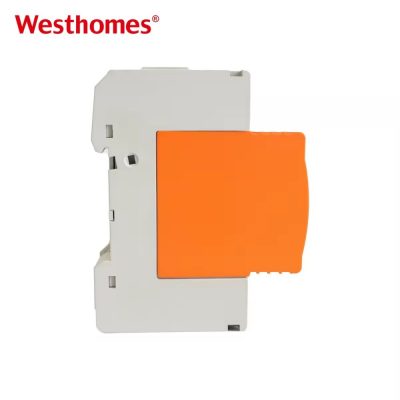
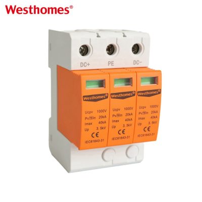
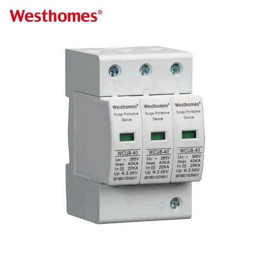
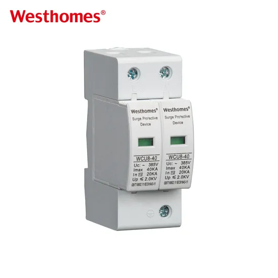
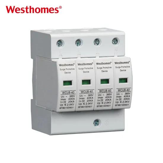
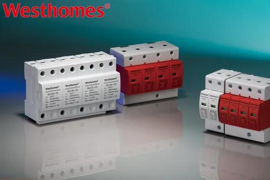
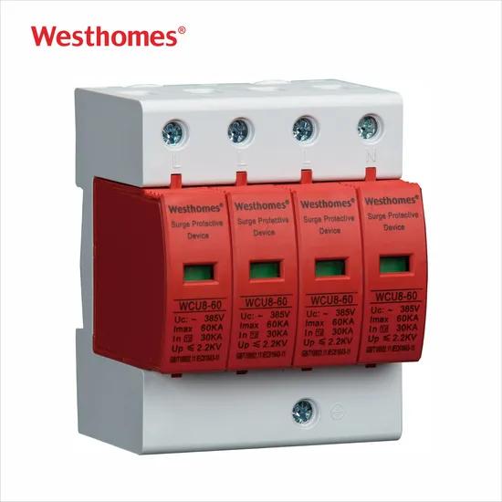
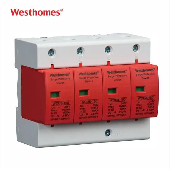
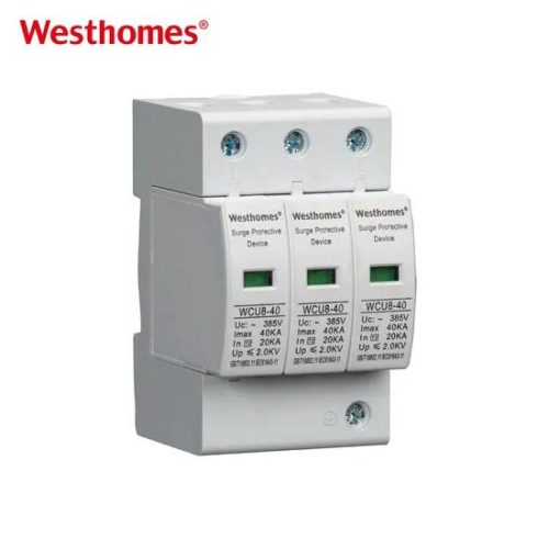
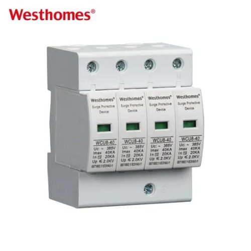
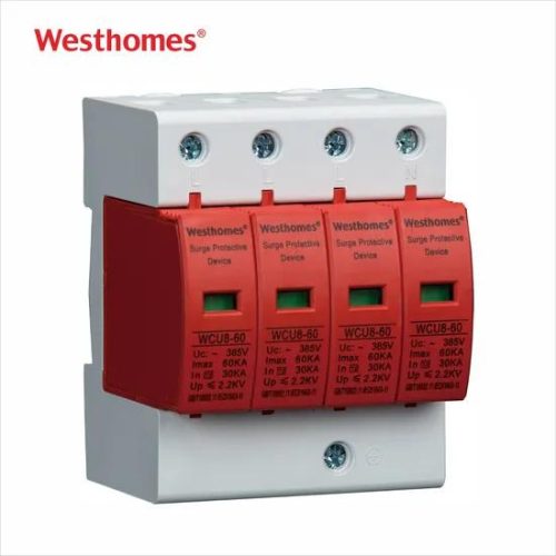
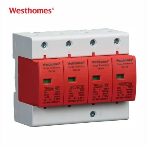
WCU8 series surge arrester mainly applies at power line of AC 50Hz/60Hz, rated operational voltage 230V and 400V to limit instantaneous over-voltage (lightning induction and switching over-voltage). It makes the protected electrical device and parts lower one level at occasion of higher over- voltage category, and lower down the voltage further when appled at terminal to protect devices like TV set, high fidelity sound, air conditioner and computer. It can also matched with other modular and digital electrics to form combination one of lightning proof inductive.
| Pole | 1P, 2P, 3P, 4P |
| Voltage | AC 110/230V/400V |
| kA | 10, 20, 30, 40, 60, 80, 100 |
| Width | 18, 36, 54, 72mm |
| kV | Up≤1.5V–2.5KV |
| Model | WCU8-D10 | WCU8-D20 | WCU8-C30 | WCU8-C40 | WCU8-C60 | WCU8-B80 | WCU8-B100 |
| Rated operation voltage Uo | 230V/400V | 230V/400V | 110V/230V/400V | 230V/400V | 230V/400V | 230V/400V | 230V/400V |
| Max continuous operation voltage Ue | 275V/385V | 320V/385V | 320V, 400V, 420V, 440V | 140V, 320V, 400V, 420V, 440V | 320V, 385V, 420V | 320V, 385V, 420V | 320V, 385V, 420V, 440V |
| Holding level Up | 0.7/1.0kV | 1.2/1.5kV | 1.4/1.8kV | 1.4/2.0kV | 1.5/2.0kV | 2.0/2.4kV | 2.2/2.8kV |
| Max discharge current Imax | 10kA | 20kA | 30kA | 40kA | 60kA | 80kA | 100kA |
| Nominal discharge current | 5kA | 10kA | 15kA | 20kA | 30kA | 40kA | 60kA |
| Response time S | <25 | ||||||
| Operation environment | -40ºC~+85ºC | ||||||
| Selection area of enter wire | 6mm2 | 6mm2 | 10mm2 | 10mm2, 16mm2 | 10mm2, 16mm2 | 10mm2, 16mm2 | 16mm2, 25mm2 |
| Section area of enter ground lead mm2 | 10mm2 | 10mm2 | 16mm2 | 10mm2, 25mm2 | 16mm2, 25mm2 | 25mm2 | 25mm2, 35mm2 |
| Type selection of fuse, circuit breaker | 10A, 16A | 16A, 25A | 25A, 32A | 32A | 32A, 63A | 63A | 63A |
An SPD is a parallel-connected device that protects electrical installations and sensitive equipment from transient overvoltages caused by lightning strikes or switching surges. Normally high-impedance, it abruptly becomes low-impedance during a surge, diverting the surge current safely to earth and clamping the voltage to a safe level. It does not replace overcurrent protection — it complements it.
Inside are voltage-limiting components — typically metal-oxide varistors (MOVs) and/or gas discharge tubes (GDTs) — connected between line conductors and earth. During a normal 230/400 V supply the component is non-conducting; when a fast voltage transient exceeds its threshold, it conducts, shunting the surge current to earth and limiting the residual voltage across the protected equipment. Once the surge passes, the device returns to its high-impedance state.
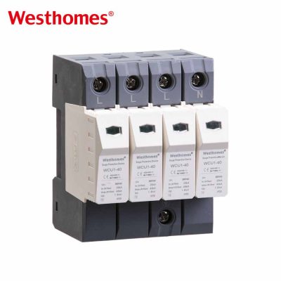
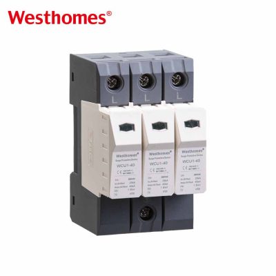
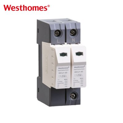
A 4-pole SPD is used in three-phase (3P+N) systems and has four protected mode combinations: L1–PE, L2–PE, L3–PE, and N–PE. It connects between each phase and earth, and between neutral and earth. A 1- or 2-pole SPD is used on single-phase 230 V systems; a 3-pole SPD protects three phases without a dedicated neutral mode. The 4-pole version is the standard choice in three-phase distribution boards.
230 V is the phase-to-neutral (line-to-earth) voltage and 400 V is the three-phase line-to-line voltage, matching standard low-voltage distribution. The maximum continuous operating voltage (Uc) must be higher than the nominal — typically 275 V for single-phase or 385/440 V for three-phase — so the SPD does not conduct under normal voltage fluctuations. The 50/60 Hz rating confirms it is suitable for both grid frequencies used worldwide.
Type 1 (Class I) SPDs are installed at the service entrance to withstand direct lightning-stroke impulse currents (10/350 µs waveform). Type 2 (Class II) SPDs are installed in distribution boards to suppress induced and switching surges (8/20 µs waveform). Type 3 (Class III) are point-of-use SPDs close to sensitive equipment with limited discharge current capacity. A coordinated Type 1 + Type 2 cascade is commonly used on incoming boards.
Imax is the maximum surge current the SPD can discharge safely for a single impulse (8/20 µs waveform), after which it may be degraded but not destroyed. In is the nominal discharge current used for type testing, and Up (voltage protection level) is the clamping voltage the SPD lets through to the equipment. Higher Imax and lower Up mean better protection, but must be matched to the installation's exposure and co-ordination with the upstream fuse.
Most SPD modules include a visual status window (green = normal, red = failed/degraded) that changes color when the internal varistor has aged to end-of-life. Many also offer remote signaling contacts (RS) that can send a dry contact to a building-management system. When the indicator shows red, the plug-in SPD module must be replaced — the SPD has degraded and no longer provides full protection.
AC power SPDs are designed and tested to IEC 61643-11 (surge protective devices connected to low-voltage power distribution systems), which replaces the older IEC 61643-1. It defines classification, test waveforms (1.2/50 µs voltage, 8/20 µs current, 10/350 µs lightning current), marking requirements, and endurance tests. The SPD should be selected with a Uc matching the system and coordinated with the upstream back-up protector.
An SPD does not replace a lightning air-termination and earthing system; it works with it. When lightning strikes or strikes nearby, the resulting electromagnetic pulse induces overvoltages on the wiring, and the SPD diverts the surge to the general earthing system. Effective lightning protection therefore combines an external LPS (air terminals, down-conductors, earth electrodes) with properly rated SPDs at the service entrance and downstream distribution boards.
The 4P SPD is mounted in the main low-voltage distribution board (or sub-distribution board) on the load side of the main breaker, with a dedicated back-up overcurrent protective device (gG or aM fuse/MCB) upstream of it. It must be wired with short, direct connections to the busbars and a low-impedance earth conductor to maximize its clamping performance. Plug-in modules allow replacement without de-energizing the board.
* indicates a required field

 2 MB
2 MB