Get quick appointment for technical support!

Solar PV DC Circuit Breaker Sizing
Jul 05, 2026
Introduction
Solar PV systems operate under different electrical conditions compared to AC systems. Since DC current does not naturally cross zero, fault interruption is more difficult and requires dedicated DC-rated protection devices.
In PV installations, DC circuit breakers are used to protect strings, combiner boxes, and inverter inputs from overload and short-circuit faults. Incorrect sizing may lead to nuisance tripping, overheating, or reduced fault protection performance.
This guide explains the main principles of DC circuit breaker sizing in solar PV systems, including calculation methods, design factors, and typical application scenarios.
Why DC Circuit Breakers Are Different in PV Systems
Unlike AC systems, DC circuits do not have natural zero-crossing points. This means that when a fault occurs, the arc is continuous and much harder to extinguish.
Because of this, DC circuit breakers used in solar PV systems must have:
- Higher arc extinguishing capability
- DC-rated voltage compatibility (typically 600V / 1000V / 1500V DC)
- Stronger contact separation design
- Specialized internal arc control structures
Key Parameters for DC Circuit Breaker Sizing
Correct sizing of a DC circuit breaker requires evaluating multiple electrical parameters rather than focusing only on current rating.
System Voltage (Vdc)
The breaker must match the maximum system voltage of the PV array. This includes open-circuit voltage under low temperature conditions.
Typical values:
- 600V DC systems (small residential PV)
- 1000V DC systems (commercial systems)
- 1500V DC systems (utility-scale PV)
Operating Current (Isc and String Current)
The starting point is the short-circuit current of the PV module:
I=P/V
For PV string design, the practical rule is:
- String current ≈ module Isc
- Multiply by safety factor (typically 1.25)
Breaking Capacity (Icu)
This defines the maximum fault current the breaker can safely interrupt.
In PV systems:
- String level: usually lower fault current
- Combiner level: higher fault current due to parallel strings
Number of Poles
DC circuit breakers may be configured as:
- 2P (single string protection)
- 4P (dual polarity isolation or multi-string systems)
Proper pole configuration has a direct impact on arc suppression performance and safe isolation behavior.
Temperature and Derating Factors
PV systems operate in outdoor environments where temperature affects current capacity.
Higher temperature = reduced current carrying capability
This must be considered during final selection.
DC Circuit Breaker Sizing Methods in PV Systems
DC circuit breaker sizing in PV systems is not simply a matter of choosing a standard current rating. It requires understanding how photovoltaic current behaves under real operating and fault conditions, especially because DC systems do not benefit from natural current zero-crossing.
In practice, proper sizing is based on the PV module short-circuit current, system configuration, safety factors, and installation environment. The goal is to ensure that the breaker can carry normal operating current safely, while still responding correctly under fault conditions without nuisance tripping.
Determine PV Module Short-Circuit Current (Isc)
The starting point for all DC breaker sizing is the module short-circuit current (Isc), which represents the maximum current the PV module can produce under standard test conditions.
For a single string system:
String current ≈ Isc of one PV module
In real installations, this value is taken from the manufacturer datasheet and used as the baseline for all further calculations.
Apply Safety Factor for Continuous Operation
PV systems operate under long periods of high irradiance, and current can exceed nominal values. Therefore, a safety factor is applied to avoid nuisance tripping and ensure thermal stability.
A commonly used engineering factor is:
Design current = 1.25 × Isc
This factor accounts for:
- Solar irradiance variations
- Temperature effects
- Long-term continuous operation
- System design margin
Consider String and Array Configuration
The final current depends on how PV strings are connected:
- Single string: current remains equal to Isc
- Parallel strings: current increases proportionally
For example:
- 1 string → I = Isc
- 2 strings in parallel → I = 2 × Isc
- 4 strings in parallel → I = 4 × Isc
This step is especially important for combiner box design, where multiple strings are aggregated into a single output circuit.
Select Rated Current (In) of the Breaker
Once the design current is calculated, the breaker rated current should be selected from the nearest standard rating above the calculated value.
The general rule is:
- Breaker rated current ≥ Design current
- But not excessively oversized
Oversizing too much may reduce protection sensitivity and delay fault response under low-level fault conditions.
Verify DC Voltage Rating
Unlike AC systems, PV systems must consider maximum open-circuit voltage (Voc), especially under low temperature conditions where voltage increases.
The breaker must satisfy:
- Vdc rating ≥ maximum system Voc
- Including cold temperature correction factor
If this step is ignored, insulation stress and arc failure risk may increase significantly.
Check Breaking Capacity (Icu / Ics)
Although PV systems typically have lower fault current levels compared to industrial AC systems, breaking capacity still plays a key role, especially in:
- Multi-string combiner boxes
- Large-scale commercial PV plants
- Battery-hybrid systems
The selected breaker must be capable of safely interrupting the maximum possible fault current at its installation point.
Apply Environmental Derating Factors
Finally, installation conditions must be considered, especially for outdoor PV systems:
- High ambient temperature reduces current carrying capacity
- Poor ventilation increases thermal stress
- Enclosed combiner boxes may require additional derating
Manufacturers usually provide derating curves that should be applied before final selection.
DC Circuit Breaker Placement in PV Systems
The performance of a DC circuit breaker in a photovoltaic system does not depend only on its electrical rating, but also on where it is installed within the system architecture. Different placement points are exposed to different current levels, fault risks, and operational requirements. Therefore, correct positioning plays a key role in ensuring effective protection and system coordination.
In practical PV design, DC circuit breakers are typically installed at several key points, each serving a different protective purpose within the energy flow from the solar modules to the inverter.
PV String Level Protection (Inside Combiner Box)
At the string level, DC circuit breakers are used to isolate individual PV strings. This allows maintenance or fault isolation without shutting down the entire system.
Typical characteristics at this level:
- Relatively low current per string
- High number of protection devices in one enclosure
- Focus on isolation and maintenance safety
This is one of the most common installation points for small and medium-scale PV systems.
Combiner Box Output Circuit Protection
At this stage, multiple PV strings are combined into a single output circuit. As a result, current levels increase significantly, and the breaker must be selected based on the total combined current.
Key considerations:
- Higher current due to parallel strings
- Increased fault energy level
- Stronger requirement for breaking capacity
This position plays a key role in protecting downstream equipment and cables.
Inverter DC Input Protection
DC circuit breakers installed at the inverter input act as both a protection and isolation device. They ensure that the inverter can be safely disconnected from the PV array during maintenance or emergency situations.
Key functions include:
- Safe isolation of inverter DC input
- Protection against upstream faults
- Maintenance switching point
This location requires careful coordination with inverter specifications.
Battery Storage DC Interface (Hybrid Systems)
In hybrid solar + storage systems, DC circuit breakers are also used between the battery bank, charge controller, and inverter. These breakers must handle bidirectional current flow depending on system design.
Important considerations:
- Bidirectional current behavior
- Higher fault current in storage systems
- Coordination with battery management system (BMS)
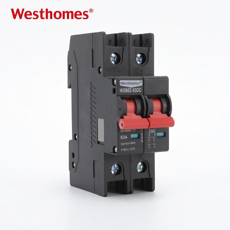
WESTHOMES Product Example: WSB6Z-63DC PV DC Circuit Breaker
To better understand how DC circuit breakers are applied in real photovoltaic systems, it is useful to look at a typical product specification used in PV string and combiner box protection.
The WESTHOMES WSB6Z-63DC series is designed specifically for photovoltaic DC applications, providing reliable overload and short-circuit protection in DC circuits. It is suitable for use in residential, commercial, and utility-scale solar systems.
Key Technical Parameters
The WSB6Z-63DC series is engineered for standard PV system requirements, offering flexible configurations and stable performance under DC conditions.
| Parameter | Specification |
| Rated current (In) | 1A – 63A |
| Rated voltage (Ue) | DC 300V / 600V / 750V / 900V / 1000V / 1200V |
| Poles | 1P / 2P / 3P / 4P |
| Breaking capacity (Icu/Ics) | 6kA |
| Standard compliance | IEC 60947-2 |
| Application type | PV DC circuit protection |
| Mounting type | DIN rail installation |
Product Features in PV Applications
In practical solar installations, the WSB6Z-63DC provides several advantages:
- Reliable protection for PV string circuits
- Suitable for high-voltage DC environments up to 1200V
- Compact DIN-rail design for combiner box integration
- High short-circuit breaking capability for fault conditions
- Suitable for both residential and commercial PV systems
Typical Application Position
This type of DC circuit breaker is commonly installed in:
- PV string combiner boxes
- DC output circuits from PV arrays
- Inverter DC input isolation points
- Maintenance and emergency disconnection points
Proper placement ensures safe isolation, fault protection, and maintenance flexibility across the entire PV system.
Summary
The WSB6Z-63DC series represents a typical photovoltaic DC circuit breaker designed for modern solar systems. Its voltage range, breaking capacity, and modular pole configuration make it suitable for a wide range of PV applications, from residential rooftops to large-scale solar farms.
DC Circuit Breaker Placement in PV Systems
The performance of a DC circuit breaker in a photovoltaic system does not depend only on its electrical rating, but also on where it is installed within the system architecture. Different placement points are exposed to different current levels, fault risks, and operational requirements. Therefore, correct positioning plays a key role in ensuring effective protection and system coordination.
In practical PV design, DC circuit breakers are typically installed at several key points, each serving a different protective purpose within the energy flow from the solar modules to the inverter.
PV String Level Protection (Inside Combiner Box)
At the string level, DC circuit breakers are used to isolate individual PV strings. This allows maintenance or fault isolation without shutting down the entire system.
Typical characteristics at this level:
- Relatively low current per string
- High number of protection devices in one enclosure
- Focus on isolation and maintenance safety
This is one of the most common installation points for small and medium-scale PV systems.
Combiner Box Output Circuit Protection
At this stage, multiple PV strings are combined into a single output circuit. As a result, current levels increase significantly, and the breaker must be selected based on the total combined current.
Key considerations:
- Higher current due to parallel strings
- Increased fault energy level
- Stronger requirement for breaking capacity
This position plays a key role in protecting downstream equipment and cables.
Inverter DC Input Protection
DC circuit breakers installed at the inverter input act as both a protection and isolation device. They ensure that the inverter can be safely disconnected from the PV array during maintenance or emergency situations.
Key functions include:
- Safe isolation of inverter DC input
- Protection against upstream faults
- Maintenance switching point
This location requires careful coordination with inverter specifications.
Battery Storage DC Interface (Hybrid Systems)
In hybrid solar + storage systems, DC circuit breakers are also used between the battery bank, charge controller, and inverter. These breakers must handle bidirectional current flow depending on system design.
Important considerations:
- Bidirectional current behavior
- Higher fault current in storage systems
- Coordination with battery management system (BMS)
Application Scenarios
DC circuit breakers are widely used across a variety of photovoltaic and energy storage systems. Their role is not only to provide overcurrent and short-circuit protection, but also to ensure safe isolation during maintenance and system configuration changes. Depending on the system scale and design architecture, their application requirements can vary significantly.
In most real-world PV projects, DC circuit breakers are selected based on system voltage level, number of PV strings, and whether energy storage is integrated into the system.
Residential Rooftop Solar Systems
In residential PV systems, DC circuit breakers are typically installed between PV strings and the inverter. Their main function is to provide safe isolation during maintenance and protect against string-level faults.
Key characteristics:
- Low to medium system voltage (600V–1000V DC)
- Simple string configuration
- Focus on safety isolation and basic fault protection
Commercial Rooftop and Building PV Systems
Commercial systems usually involve multiple strings and combiner boxes, requiring more coordinated protection design. DC circuit breakers are used both at string level and combiner output level.
Key characteristics:
- Multiple PV strings connected in parallel
- Higher total system current
- Requirement for selective protection coordination
Utility-Scale Solar Farms
In utility-scale PV installations, DC circuit breakers are key components in combiner boxes and array management systems. These systems operate at high voltage levels and require devices with high breaking capacity.
Key characteristics:
- High voltage systems (1000V–1500V DC)
- Large number of parallel strings
- High fault current potential at combiner level
- Strict coordination with protection relays and fuses
Hybrid Solar + Energy Storage Systems
Hybrid systems integrate PV arrays with battery storage, requiring DC circuit breakers at multiple energy flow points, including PV input, battery interface, and inverter DC side.
Key characteristics:
- Bidirectional current flow
- Complex energy management system
- Higher system reliability requirements
- Coordination with battery management system (BMS)
Off-Grid Solar Power Systems
Off-grid systems rely entirely on solar power and storage, making DC protection devices play a key role in stable and safe operation. DC circuit breakers are used to isolate PV arrays, batteries, and DC loads.
Key characteristics:
- No utility grid connection
- High dependence on system reliability
- Multiple DC loads and storage interfaces
- Frequent maintenance isolation requirements
Standards and Compliance
DC circuit breakers used in photovoltaic systems must comply with international electrical standards to ensure safe operation, reliable performance, and compatibility with global installation practices. These standards define requirements for voltage rating, breaking capacity, insulation performance, and testing conditions under both normal and fault states.
Compliance is particularly important in PV applications because DC fault conditions behave differently from AC systems, and improper device selection or uncertified products may lead to unsafe arc interruption or system failure.
IEC Standards for DC Circuit Breakers
The most widely referenced international standards include:
- IEC 60947-2
Applies to low-voltage circuit breakers, defining performance requirements for overload and short-circuit protection. - IEC 60947-3
Covers switches, disconnectors, and switch-disconnectors used for isolation and load switching functions. - IEC 60947-6-1
Applies to automatic transfer switching equipment and multi-function switching systems. - IEC 62548
Specifies design and installation requirements for photovoltaic (PV) arrays.
Voltage and DC Rating Compliance
Because PV systems operate at higher DC voltages than conventional systems, circuit breakers must be specifically rated for DC operation. Key compliance considerations include:
- Rated operational voltage (typically 600V, 1000V, or 1500V DC)
- Correct polarity and insulation coordination
- Adequate arc extinguishing capability for DC fault interruption
Using AC-rated devices in DC applications is not compliant and may lead to serious safety risks.
Breaking Capacity and Safety Compliance
Standards also define the required breaking capacity (Icu / Ics) under different fault conditions. In PV systems, this ensures that the breaker can safely interrupt the maximum possible short-circuit current without damage or arc failure.
Proper compliance ensures:
- Safe interruption of fault currents
- Reduced risk of arc flash incidents
- Long-term mechanical and electrical reliability
Installation and System Compliance
Beyond product standards, PV system design must also comply with installation codes and engineering guidelines. These include:
- Proper cable sizing and thermal coordination
- Correct enclosure protection (IP rating compliance)
- Adequate clearance for heat dissipation
- Compliance with local electrical regulations
Conclusion
Correct sizing of a solar PV DC circuit breaker is directly related to system safety, reliability, and long-term performance. Unlike AC systems, DC circuits require special attention to voltage rating, arc suppression, and fault current behavior.
A properly selected DC breaker helps protect equipment and ensures safe system isolation during maintenance and fault conditions.

--- END ---
In this blog
Featured Articles
Get A Free Quote
