Get quick appointment for technical support!

Arc Flash Hazard Analysis for Low Voltage Systems — NFPA 70E Practical Guide
Jul 11, 2026
Introduction
Working on energized low-voltage electrical equipment involves more than the risk of electric shock. An arc flash can release intense heat, pressure waves, molten metal, and flying debris within milliseconds, potentially causing serious injuries and equipment damage even in systems operating below 1000V.
NFPA 70E provides a practical framework for identifying arc flash hazards, assessing electrical risks, and selecting appropriate protective measures before work begins. This guide explains how arc flash hazard analysis is carried out in low-voltage systems, the factors that influence the results, and how the analysis supports safer operation and maintenance.
What Is an Arc Flash?
An arc flash is a sudden release of energy caused by an electrical arc between conductors or between a conductor and ground. When insulation fails or an unintended conductive path is created, electrical current can travel through the air, generating an arc with extremely high temperatures, intense light, pressure waves, and molten metal particles.
Unlike an electric shock, which affects the body through direct contact with electricity, an arc flash can cause severe injuries without physical contact. The intense thermal energy released during an arc flash may result in serious burns, eye injuries, hearing damage, and extensive equipment destruction within a fraction of a second.
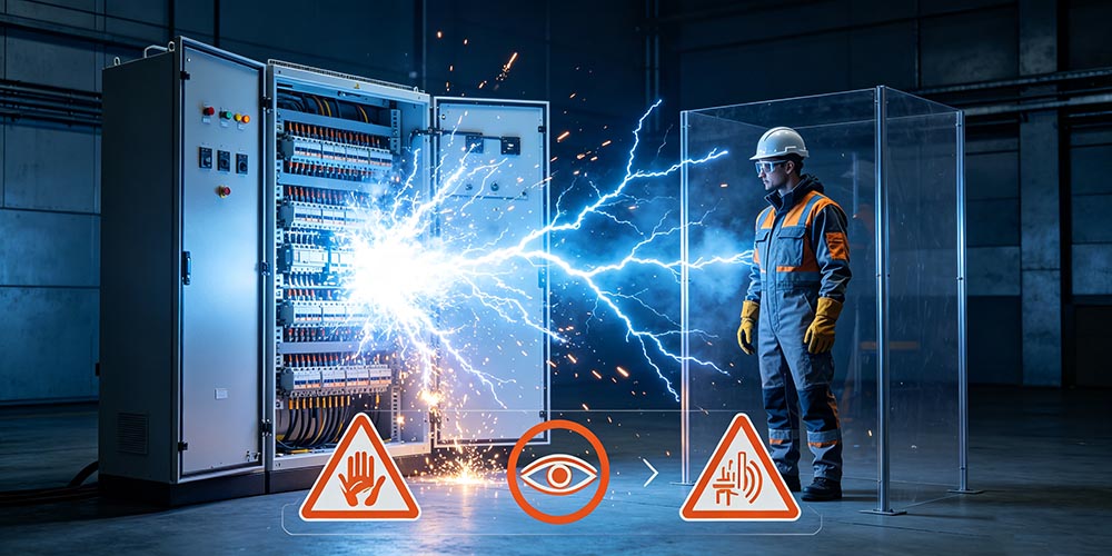
Although arc flashes are more commonly associated with medium- and high-voltage installations, they can also occur in low-voltage systems. Distribution boards, motor control centers (MCCs), switchboards, and panelboards all present potential arc flash hazards when faults occur under energized conditions.
How Does an Arc Flash Occur?
An arc flash typically develops when electrical insulation breaks down or conductive materials bridge energized parts. Common triggering conditions include loose connections, damaged insulation, equipment failure, contamination from dust or moisture, accidental contact with live components, or the use of improper tools during maintenance.
Once an arc is established, temperatures can rise to several thousand degrees Celsius within milliseconds. At the same time, expanding hot gases and pressure waves may damage nearby equipment and create hazardous working conditions for personnel.
Why Arc Flash Analysis Is Required
Arc flash hazard analysis helps identify the potential consequences of an electrical arc fault before maintenance or operation begins. Rather than relying only on personal protective equipment (PPE), the analysis evaluates system conditions, fault energy, and protective device performance to determine the level of risk and the appropriate safety measures.
By understanding where arc flash hazards may occur and how severe they could be, facility operators can improve workplace safety, reduce equipment damage, and support compliance with electrical safety standards.
Protect Personnel from Arc Flash Injuries
Arc flash analysis estimates the potential incident energy released during a fault, helping determine the level of thermal exposure workers may face. This information allows employers to establish safer working procedures before personnel approach energized equipment.
Determine Incident Energy
Incident energy is one of the main results of an arc flash study. It represents the amount of thermal energy that could reach a worker at a specified working distance and is commonly expressed in cal/cm².
The calculated value is used to evaluate the severity of an arc flash event and supports decisions related to protective equipment and safe working practices.
Establish the Arc Flash Boundary
The Arc Flash Boundary defines the minimum safe distance from energized equipment where the incident energy reaches 1.2 cal/cm², the threshold at which a second-degree burn may occur.
Personnel entering this boundary should follow the required safety procedures and wear appropriate protective equipment.
Select Appropriate PPE
The results of the analysis help determine the required arc-rated clothing, face shields, gloves, helmets, and other PPE for specific maintenance tasks.
Selecting PPE based on actual incident energy provides a more suitable level of protection than relying on assumptions alone.
Support Compliance with Safety Standards
Arc flash hazard analysis supports compliance with electrical safety standards such as NFPA 70E, IEEE 1584, and applicable workplace safety regulations. It also provides documented information for safety management, maintenance planning, and equipment labeling.
Reduce Equipment Damage and Downtime
Understanding the potential fault energy allows engineers to optimize protection settings, improve coordination between protective devices, and reduce the impact of electrical faults on equipment.
This contributes to faster fault isolation, shorter maintenance periods, and improved system availability.
Common Causes of Arc Flash in Low Voltage Systems
Arc flashes can occur whenever an unintended electrical arc develops between energized conductors or between a conductor and ground. In low-voltage systems, these events are often triggered by a combination of equipment condition, environmental factors, and human error rather than a single failure.
Understanding the most common causes helps maintenance personnel identify potential hazards before work begins and reduce the likelihood of an arc flash incident.
Loose or Poor Electrical Connections
Loose terminals, improperly tightened cable lugs, or worn contact surfaces can create high-resistance points within a circuit. As current flows through these areas, excessive heat may build up, eventually damaging insulation and initiating an electrical arc.
Regular inspection and proper torque tightening can significantly reduce the risk of connection-related failures.
Equipment Failure or Aging
Over time, electrical equipment may deteriorate due to thermal cycling, vibration, mechanical wear, or aging insulation materials. Components such as circuit breakers, contactors, and busbars may no longer operate as intended, increasing the possibility of an internal arc fault.
Routine maintenance and timely replacement of aging components help maintain reliable system performance.
Insulation Breakdown
Damaged or degraded insulation may allow electrical current to travel through unintended paths. Cracked cable insulation, worn busbar supports, or contaminated insulating materials can all contribute to arc initiation.
Insulation testing is an effective way to identify potential problems before failures occur.
Human Error During Maintenance
Many arc flash incidents occur during maintenance rather than normal operation. Examples include accidental contact with energized parts, failure to isolate power sources, incorrect wiring, or using unsuitable procedures while equipment remains energized.
Following established electrical safety procedures greatly reduces these risks.
Improper Tools or Test Equipment
Using damaged, conductive, or non-insulated tools can unintentionally bridge energized conductors and create an electrical arc. Test instruments with incorrect ratings may also fail under fault conditions.
Only insulated tools and properly rated test equipment should be used when working on electrical systems.
Dust, Moisture, and Environmental Contamination
Dust accumulation, moisture, corrosion, or conductive contaminants inside electrical enclosures can reduce insulation performance and increase the likelihood of electrical tracking or flashover.
Keeping electrical equipment clean and operating within its specified environmental conditions helps reduce these risks.
Foreign Objects and Accidental Contact
Metal tools, loose hardware, conductive debris, or accidental contact with live parts during maintenance can create an unintended electrical path and trigger an arc flash event.
Good housekeeping practices and controlled work procedures help minimize these hazards.
Arc Flash Hazard Analysis Process
An arc flash hazard analysis follows a structured engineering process that evaluates how an electrical system behaves under fault conditions. The objective is to estimate the potential incident energy, determine safe working boundaries, and identify suitable protective measures before personnel perform maintenance or troubleshooting.
Although the exact methodology may vary depending on project requirements, most arc flash studies follow a similar sequence of data collection, calculation, verification, and documentation.
Step 1: Collect System Data
The first step is to gather complete electrical system information. Accurate data provides the foundation for all subsequent calculations, and missing or outdated information can affect the accuracy of the analysis.
Typical information includes:
- Single-line diagrams
- Transformer ratings and impedance
- Utility short-circuit data
- Cable sizes and lengths
- Switchboards and panel ratings
- Circuit breaker and fuse specifications
- Protective device settings
Whenever possible, field verification should be performed to confirm that the installed equipment matches the design documentation.
Step 2: Calculate Available Fault Current
After system data is collected, engineers calculate the available short-circuit current at each electrical bus or equipment location. This value represents the maximum current that could flow during a fault.
Fault current depends on several factors, including transformer capacity, system impedance, conductor characteristics, and the utility supply. Higher fault current generally results in greater arc energy if the protective device does not operate quickly.
Step 3: Determine Protective Device Clearing Time
The operating time of circuit breakers or fuses has a direct influence on the amount of incident energy released during an arc fault. Faster fault clearing limits the duration of the arc and reduces thermal exposure.
During this step, engineers review time-current characteristic (TCC) curves and protective device settings to determine how quickly each device will interrupt a fault under different operating conditions.
Step 4: Calculate Incident Energy
Using the collected system data, fault current, clearing time, and working distance, engineers calculate the incident energy at each piece of equipment. The result is typically expressed in cal/cm² and represents the thermal energy that could reach a worker during an arc flash event.
This value forms the basis for selecting PPE and evaluating the severity of the hazard.
Step 5: Establish the Arc Flash Boundary
Based on the calculated incident energy, the Arc Flash Boundary is established. This boundary defines the minimum distance at which the incident energy falls to 1.2 cal/cm², the threshold commonly associated with the onset of a second-degree burn.
Personnel entering this boundary should follow appropriate safety procedures and wear arc-rated PPE.
Step 6: Verify Results and Apply Safety Measures
The final step is to review the analysis results and apply them to practical safety management. This includes preparing arc flash labels, selecting appropriate PPE, reviewing protective device coordination, and updating maintenance procedures where necessary.
Arc flash studies should also be reviewed whenever significant system modifications are made, such as equipment replacement, capacity expansion, or changes to protection settings.
Key Factors Affecting Arc Flash Energy
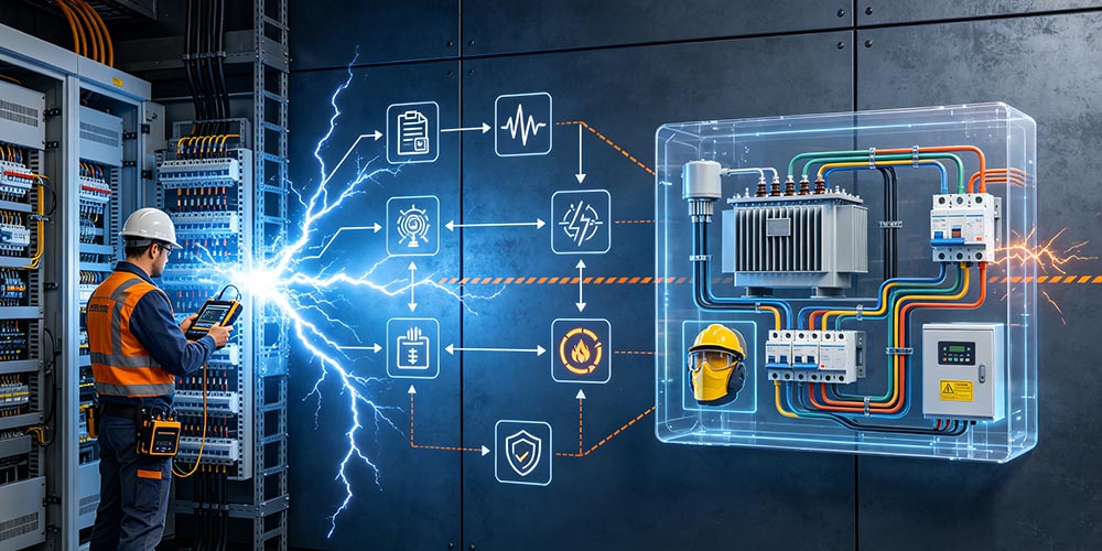
The severity of an arc flash event is influenced by several electrical and installation-related factors rather than a single condition. During an arc flash hazard analysis, engineers evaluate these variables to estimate the incident energy that may be released if a fault occurs.
Understanding how these factors interact helps improve protection strategies, optimize protective device settings, and reduce the potential impact of electrical faults.
| Factor | Influence on Arc Flash Energy |
| Available Fault Current | Higher fault current generally results in greater incident energy if the protective device clearing time remains the same. |
| Protective Device Clearing Time | Longer operating time allows the arc to exist for a longer period, increasing the total energy released. |
| Working Distance | The closer a worker is to the arc source, the greater the thermal energy exposure. |
| System Voltage | Voltage affects arc stability and influences the characteristics of the electrical arc. |
| Equipment Enclosure | Enclosed equipment can concentrate heat and pressure, increasing incident energy compared with open-air conditions. |
| Equipment Condition | Poor maintenance, damaged insulation, or loose connections may increase the likelihood and severity of an arc fault. |
Arc Flash Labels and Equipment Marking
Arc flash labels provide workers with essential safety information before they perform inspection, maintenance, or troubleshooting on energized electrical equipment. Rather than replacing a risk assessment, these labels communicate the results of an arc flash study and help personnel understand the potential hazards at a specific piece of equipment.
Proper equipment marking also supports safer work practices by ensuring that operators and maintenance personnel can quickly identify electrical hazards and apply the appropriate protective measures before beginning any task.
Information Commonly Found on an Arc Flash Label
Although the label format may vary depending on company practices or local regulations, most arc flash labels include the following information:
- Equipment identification
- Nominal system voltage
- Arc Flash Boundary
- Incident energy at the specified working distance (cal/cm²)
- Required PPE level or arc-rated clothing
- Working distance used for the calculation
- Date of the arc flash study or last review
These details allow qualified personnel to evaluate the level of risk before opening or servicing energized equipment.
Why Arc Flash Labels Are Necessary
Arc flash labels improve safety by making hazard information immediately visible at the point of work. Instead of searching through engineering reports, maintenance personnel can quickly identify the expected incident energy and determine the appropriate protective measures.
Labels also help standardize safety procedures across different facilities and support compliance with electrical safety programs.
When Should Labels Be Updated?
Arc flash labels should be reviewed whenever changes are made to the electrical system that may affect fault current levels or protective device performance. Typical situations include:
- Replacement of transformers or switchgear
- Changes to protective device settings
- Installation of new equipment
- Expansion of the electrical distribution system
- Completion of a new arc flash study
Keeping labels up to date helps ensure that the displayed information reflects the actual operating conditions of the electrical system.
Example of Typical Arc Flash Label Information
| Label Item | Description |
| Equipment ID | Identifies the electrical equipment |
| System Voltage | Nominal operating voltage |
| Incident Energy | Thermal energy at the specified working distance |
| Arc Flash Boundary | Minimum distance requiring arc flash protection |
| Working Distance | Distance used for the incident energy calculation |
| PPE Requirement | Recommended arc-rated protective equipment |
| Study Date | Date of the latest arc flash assessment |
PPE Selection According to NFPA 70E
NFPA 70E recommends selecting personal protective equipment (PPE) based on the results of an arc flash risk assessment rather than using the same equipment for every task. The required level of protection depends on factors such as incident energy, working distance, and the type of electrical work being performed.
Selecting suitable PPE helps reduce the risk of burn injuries if an arc flash occurs. However, PPE should be considered one part of an overall electrical safety program that also includes hazard assessment, safe work practices, and proper equipment maintenance.
Common PPE Used for Arc Flash Protection
Depending on the calculated incident energy, personnel may need to wear different types of arc-rated protective equipment, including:
- Arc-rated clothing
- Arc-rated face shield or hood
- Safety helmet
- Safety glasses or goggles
- Rubber insulating gloves with leather protectors
- Hearing protection
- Safety footwear
The selected equipment should provide an arc rating that is equal to or greater than the calculated incident energy for the task.
PPE Selection Guide
| Electrical Task | Typical PPE Requirement |
| Visual inspection with covers closed | Standard safety PPE as required by site procedures |
| Operating electrical equipment | Arc-rated PPE may be required based on the risk assessment |
| Testing energized circuits | Arc-rated clothing, insulated gloves, face shield, and other required PPE |
| Maintenance inside energized equipment | PPE selected according to the calculated incident energy |
Proper Use of PPE
Even properly selected PPE cannot eliminate electrical hazards if it is used incorrectly or is in poor condition. Before each task, workers should inspect protective clothing and equipment for signs of wear, damage, contamination, or expired certification.
PPE should also fit properly and be used together with insulated tools, lockout/tagout procedures, and other safety measures required by the work environment.
Best Practices for Reducing Arc Flash Risks
Reducing arc flash risk involves more than wearing personal protective equipment. A combination of proper equipment design, routine maintenance, safe work procedures, and personnel training can significantly reduce the likelihood of an arc flash event and minimize its consequences if one occurs.
The following practices are widely recommended for improving electrical safety in low-voltage systems.
De-Energize Equipment Whenever Possible
Whenever practical, electrical equipment should be completely de-energized before inspection, maintenance, or repair. Eliminating the electrical source is one of the most effective ways to reduce arc flash exposure.
Follow Lockout/Tagout (LOTO) Procedures
Proper Lockout/Tagout procedures help ensure that equipment cannot be accidentally energized while maintenance work is in progress. This reduces the possibility of unexpected electrical faults during servicing.
Perform Routine Equipment Maintenance
Loose terminals, worn contacts, damaged insulation, and accumulated dust can all increase the likelihood of an arc fault. Regular inspection, cleaning, and maintenance help keep equipment in good operating condition.
Verify the Absence of Voltage
Before beginning work, use properly rated test instruments to verify that the equipment is de-energized. Never assume that a circuit is safe based solely on switch position or operating indicators.
Use Proper Tools and Test Equipment
Only insulated tools and electrical test instruments with appropriate voltage ratings should be used. Damaged or unsuitable equipment may increase the chance of accidental contact or electrical faults.
Keep Electrical Equipment Clean
Dust, moisture, and conductive contaminants inside electrical enclosures can reduce insulation performance and contribute to flashover. Regular cleaning helps maintain reliable insulation and safe operating conditions.
Train Qualified Personnel
Personnel who work on energized electrical equipment should receive appropriate training on electrical hazards, safe work practices, PPE use, and emergency procedures. Regular refresher training helps maintain awareness of electrical safety requirements.
Review Arc Flash Studies Regularly
Arc flash studies should be reviewed whenever the electrical system is modified, such as after equipment replacement, system expansion, or changes to protective device settings. Keeping the analysis current ensures that safety measures remain aligned with actual operating conditions.
Common Mistakes During Arc Flash Assessment
An arc flash study is only as accurate as the data and assumptions used during the analysis. Incomplete system information, outdated documentation, or incorrect engineering assumptions can lead to inaccurate incident energy calculations and inappropriate safety recommendations.
Recognizing these common mistakes helps improve the quality of the analysis and ensures that protective measures reflect actual operating conditions.
Using Outdated System Drawings
Electrical systems are often modified over time through equipment replacement, capacity expansion, or panel upgrades. Performing an arc flash study using outdated single-line diagrams may result in calculations that no longer represent the actual installation.
Ignoring Equipment Modifications
Changes such as replacing transformers, installing new switchgear, or adding distribution panels can significantly affect available fault current and protective device coordination. These modifications should always be included in the analysis.
Not Updating Protective Device Settings
Circuit breaker and relay settings directly influence fault clearing time. If protection settings have been adjusted but the arc flash study has not been updated, the calculated incident energy may no longer be accurate.
Assuming PPE Alone Solves the Risk
Personal protective equipment helps reduce the severity of injuries, but it does not eliminate the electrical hazard itself. Engineering controls, safe work procedures, equipment maintenance, and proper training remain equally important.
Skipping Equipment Inspection
Relying only on design documents without verifying actual equipment conditions may overlook loose connections, damaged insulation, or unauthorized modifications that affect arc flash risk.
Using Incorrect Working Distance
Incident energy is calculated based on a specified working distance. Using an unrealistic distance may overestimate or underestimate the thermal exposure experienced by personnel during maintenance.
Failing to Review the Study Regularly
An arc flash study should not be treated as a one-time project. As electrical systems evolve, periodic reviews help ensure that calculations, labels, and safety procedures continue to match the current installation.
Applications
Arc flash hazard analysis is applicable to almost every low-voltage electrical installation where personnel may work on or near energized equipment. Although the level of risk varies by industry and system configuration, performing an arc flash study helps organizations better understand electrical hazards, improve maintenance planning, and establish safer work procedures.
The following are some of the most common applications for arc flash hazard analysis in low-voltage power distribution systems.
| Application | Typical Equipment and Purpose |
| Manufacturing Plants | Motor control centers (MCCs), switchboards, and production equipment where frequent maintenance is required. |
| Commercial Buildings | Main distribution boards, panelboards, and electrical rooms supplying offices, shopping centers, and public facilities. |
| Data Centers | Low-voltage switchgear, UPS systems, and power distribution units that require reliable and continuous power. |
| Hospitals | Emergency power systems, distribution panels, and critical medical equipment with strict electrical safety requirements. |
| Renewable Energy Facilities | Low-voltage distribution equipment serving solar PV systems, battery energy storage systems (BESS), and inverters. |
| Utility and Infrastructure Projects | Low-voltage substations, auxiliary power systems, and industrial distribution equipment supporting public infrastructure. |
NFPA 70E and Related Standards
Arc flash hazard analysis is not based on a single document. In practice, several standards work together to provide the framework for electrical safety, hazard assessment, and engineering calculations. Understanding how these standards relate to each other helps ensure that an arc flash study is both technically accurate and compliant with workplace safety requirements.
NFPA 70E – Electrical Safety in the Workplace
NFPA 70E is the primary workplace electrical safety standard in the United States. It focuses on protecting personnel who work on or near energized electrical equipment.
The standard provides guidance on:
- Electrical hazard identification
- Risk assessment procedures
- Arc flash boundaries
- Selection of personal protective equipment (PPE)
- Safe work practices
- Training requirements for qualified personnel
NFPA 70E does not prescribe a single calculation method for arc flash energy. Instead, it requires employers to perform an arc flash risk assessment and use recognized engineering methods to determine the level of protection needed.
IEEE 1584 – Arc Flash Calculation Method
IEEE 1584 is the most widely used engineering standard for calculating incident energy and arc flash boundaries.
It provides methods for:
- Calculating available fault current
- Estimating arcing current
- Determining protective device clearing time
- Calculating incident energy
- Establishing arc flash boundaries
In many projects, NFPA 70E defines what must be done, while IEEE 1584 provides the engineering method for calculating the results.
OSHA – Workplace Safety Enforcement
OSHA is the U.S. regulatory agency responsible for enforcing workplace safety requirements. While OSHA regulations do not contain detailed arc flash calculation procedures, they require employers to protect workers from recognized electrical hazards.
Following NFPA 70E is widely accepted as a practical way to demonstrate compliance with OSHA electrical safety obligations.
NEC – Electrical Installation Requirements
NEC focuses on the design and installation of electrical systems. It helps reduce the likelihood of electrical faults through proper equipment selection, conductor sizing, grounding, and installation practices.
While NEC is not an arc flash calculation standard, it supports arc flash risk reduction by promoting safer electrical installations.
How These Standards Work Together
| Standard | Primary Purpose |
| NFPA 70E | Electrical safety work practices and risk assessment |
| IEEE 1584 | Arc flash calculation methodology |
| OSHA | Workplace safety enforcement |
| NEC | Electrical system installation requirements |
Frequently Asked Questions (FAQ)
Q1 What is the difference between an arc flash and an electric shock?
An electric shock occurs when electrical current passes through the human body, while an arc flash is the rapid release of thermal energy caused by an electrical arc. An arc flash can cause severe burns, pressure injuries, and equipment damage even without direct contact with energized conductors.
Q2 Is arc flash analysis required for low-voltage systems?
Yes. Although low-voltage systems generally operate below 1000V, they can still produce enough incident energy to create serious arc flash hazards. An arc flash analysis helps evaluate these risks and determine appropriate protective measures.
Q3 How often should an arc flash study be updated?
An arc flash study should be reviewed whenever significant changes are made to the electrical system, such as equipment replacement, system expansion, or modifications to protective device settings. Periodic reviews also help ensure that the analysis reflects current operating conditions.
Q4 Does wearing PPE completely eliminate arc flash risk?
No. PPE helps reduce the severity of injuries but does not eliminate the hazard itself. Safe work procedures, proper equipment maintenance, and effective risk assessment are equally important for reducing arc flash risks.
Q5 What information is included on an arc flash label?
A typical arc flash label may include the equipment identification, nominal voltage, incident energy, arc flash boundary, working distance, PPE requirements, and the date of the latest assessment.
Q6 Which standards are commonly used for arc flash hazard analysis?
Arc flash studies commonly reference NFPA 70E for workplace electrical safety, IEEE 1584 for incident energy calculations, OSHA for workplace safety regulations, and NEC for electrical installation practices.
Q7 Can regular maintenance help reduce arc flash risk?
Yes. Routine inspection and maintenance can identify loose connections, insulation deterioration, contamination, and other conditions that may increase the likelihood of an arc fault. Keeping electrical equipment in good condition contributes to a safer operating environment.
Conclusion
Arc flash hazard analysis provides a practical way to identify electrical hazards before work begins. By evaluating system conditions, calculating incident energy, and following the guidance of NFPA 70E and related standards, organizations can better understand potential risks and implement appropriate protective measures for low-voltage electrical systems.
Electrical safety is an ongoing process rather than a one-time assessment. Regular equipment maintenance, updated arc flash studies, proper PPE selection, and safe work practices all contribute to a safer working environment, reduced equipment damage, and more reliable system operation.

--- END ---
In this blog
Featured Articles
Get A Free Quote
