Get quick appointment for technical support!

How to Perform an Electrical Load Calculation – Step-by-Step Guide
Jul 15, 2026
Introduction
Electrical load calculation is one of the fundamental steps in electrical system design. Whether for residential buildings, commercial facilities, or industrial installations, accurate load calculation determines the actual power demand, required conductor size, and suitable protection devices for the electrical system.An incorrect load calculation leads to various problems: overloaded circuits, frequent breaker tripping, cable overheating, equipment damage, and reduced system reliability.
By understanding connected loads, operating conditions, and demand requirements, engineers and electricians can design safer and more efficient electrical systems. This guide walks through the load calculation process step by step, covering basic formulas, calculation methods, practical examples, and considerations for selecting protection devices.

What Is an Electrical Load Calculation?
Beyond Simply Adding Ratings
Electrical load calculation is the process of determining total electrical demand by analyzing all connected equipment, operating conditions, and expected usage patterns. The purpose is to understand how much current the electrical system will actually need to supply under normal operating conditions.
Many people assume load calculation simply means adding the power ratings of all connected devices together. Real electrical systems are more complex. Not every device operates at full capacity or runs at the same time.
Key Factors in Load Calculation
Professional load calculations consider several factors:
- Connected Load – The total rated power of all electrical equipment connected to the system.
- Demand Factor – The percentage of connected load expected to operate at the same time.
- Diversity Factor – The difference between total connected load and actual maximum demand.
- Continuous Load – Equipment expected to operate for extended periods, requiring additional design margin.
- Starting Current – The temporary high current required by motors and inductive loads during startup.
Why Load Calculation Matters
Accurate load calculation plays a central role in creating a safe and reliable electrical installation. It directly affects cable sizing, circuit breaker selection, energy efficiency, and overall system performance.
Prevent Circuit Overloading
When electrical demand exceeds the designed capacity of a circuit, excessive current causes cables and components to overheat. Load calculation keeps the system operating within safe limits.
Select Correct Protection Devices
Circuit breakers must match actual electrical demand. An undersized breaker causes unnecessary tripping; an oversized breaker may fail to provide adequate protection during overload conditions.
Improve System Efficiency
Accurate calculations prevent unnecessary oversizing of equipment, reducing installation costs and improving energy efficiency.
Meet Safety Standards and Compliance
Electrical installations must meet applicable standards and regulations. Load calculation keeps cables, breakers, and distribution equipment aligned with design requirements.
Basic Electrical Parameters You Need to Know
Before performing an electrical load calculation, several basic parameters must be understood. These values determine how much power a system consumes and how much current flows through the circuit.
Power (P)
Electrical power represents the rate at which electrical energy is consumed or converted, measured in watts (W) or kilowatts (kW).
For most electrical systems:
Single-phase: P = V × I × cosφ
Three-phase: P = √3 × V × I × cosφ
Where: P = Power (W), V = Voltage (V), I = Current (A), cosφ = Power factor.
Power factor is especially relevant for inductive loads such as motors and transformers because it affects the actual current required by the equipment.
Current (I)
Current is the amount of electrical charge flowing through a conductor. Since cables and circuit breakers are selected based on current capacity, calculating the expected current is one of the most critical steps in load calculation.
The basic formulas are:
Single-phase: I = P / (V × cosφ)
Three-phase: I = P / (√3 × V × cosφ)
The calculated current is then used to select suitable conductors and protection devices.
Voltage (V)
Voltage is the electrical potential difference that drives current through a circuit. Different applications use different voltage levels, affecting the load calculation result.
Common low-voltage systems include 120V single-phase, 230V single-phase, 400V three-phase, and 480V industrial systems. Understanding the system voltage is a prerequisite for calculating current demand.
Power Factor (cosφ)
Power factor describes the relationship between real power and apparent power. It indicates how efficiently electrical energy is converted into useful work.
Typical values: resistive loads near 1; motors and transformers usually lower. A lower power factor means higher current is required for the same power output, affecting cable sizing and protection device selection.
Types of Electrical Loads
Electrical loads are classified based on how they consume energy and affect the electrical system. Each type may require different calculation methods and protection considerations.
Resistive Loads
Resistive loads convert electrical energy mainly into heat or light, with a power factor close to 1. Common examples include electric heaters, ovens, water heaters, incandescent lighting, and heating elements.
For resistive loads, calculation is straightforward because power factor has little impact on current demand.
Example: A 230V electric heater rated at 3000W:
I = P / V = 3000 / 230 ≈ 13A
A suitable circuit breaker and cable size can be selected based on the calculated current.
Inductive Loads
Inductive loads contain coils or windings that create magnetic fields during operation. These loads usually have lower power factors and may require higher current compared to resistive loads of the same power rating. Common examples include motors, pumps, fans, compressors, and transformers.
Inductive loads demand additional attention because of high starting currents when switched on. Motor starting current can be several times higher than normal operating current, affecting circuit breaker selection.
When calculating inductive loads, engineers should account for: rated operating current, power factor, starting current, and motor duty cycle. For industrial applications, ignoring starting current leads to unnecessary breaker tripping or voltage drop problems.
Capacitive Loads
Capacitive loads store electrical energy in an electric field and are commonly used for power factor correction and energy management. Typical examples include capacitor banks, power correction equipment, and electronic power supplies.
Although capacitive loads are less common in basic load calculations, they influence system current characteristics and voltage behavior. Large capacitor installations may require special consideration during switching because they can generate temporary current surges.
Step-by-Step Electrical Load Calculation Process
Performing a load calculation requires a structured approach. The goal: determine actual system demand and use the result to select cables, circuit breakers, and other equipment. The following steps provide a practical method.
List All Electrical Loads
Create a complete load schedule that includes every electrical device connected to the system. A load schedule should include equipment name, quantity, rated power, voltage, and phase.
| Equipment | Quantity | Rated Power | Voltage | Phase |
|---|---|---|---|---|
| Lighting | 20 | 20W | 230V | Single Phase |
| Air Conditioner | 2 | 1500W | 230V | Single Phase |
| Motor | 1 | 5kW | 400V | Three Phase |
Key information to collect: equipment quantity, rated power, operating voltage, single-phase or three-phase connection, and expected operating hours. An accurate load list prevents missing equipment during calculation.
Convert Power Ratings into Current
After identifying all connected loads, convert the rated power into current values. Circuit breakers and cables are selected according to current capacity, so the calculated current is the key design value.
For single-phase: I = P / (V × cosφ)
For three-phase: I = P / (√3 × V × cosφ)
Example: A three-phase motor, 15kW, 400V, power factor 0.85:
I = 15000 / (√3 × 400 × 0.85) ≈ 25.5A
The calculated current provides the starting point for selecting the protection device.
Apply Demand Factor
In real systems, not all connected loads operate at the same time. Applying a demand factor estimates the actual maximum expected load rather than simply adding every rated power together.
Basic calculation: Demand Load = Connected Load × Demand Factor
Example: A commercial building with 100kW connected load and 0.7 demand factor:
Demand Load = 100 × 0.7 = 70kW
The system should be designed based on approximately 70kW instead of the full 100kW. Demand factors vary by application type, local regulations, and operating conditions.
Consider Continuous Loads
In electrical design, not all loads are treated the same way. Some equipment operates continuously for extended periods and requires additional margin during system sizing.
A continuous load generally operates for three hours or more under normal conditions. Examples include lighting systems, HVAC equipment, data center equipment, security systems, and industrial process equipment.
For continuous loads, designers apply an additional safety margin to prevent conductors and protection devices from operating near maximum capacity for long periods. The basic approach: Continuous Load = Rated Load × 125%.
Example: A lighting circuit with 10A continuous load:
Design current = 10A × 125% = 12.5A
The cable size and circuit breaker should be selected based on the adjusted design current, not the original load current. This improves system reliability and reduces the risk of overheating from long-term operation.
Calculate Total Load Current
After considering connected loads, demand factors, and continuous loads, determine the total design current. This value is used for selecting the main circuit breaker, distribution equipment, cable size, and verifying protection coordination.
For single-phase systems: I = P / (V × cosφ)
Example: Residential system, 6000W, 230V, power factor 1:
I = 6000 / (230 × 1) ≈ 26A
The selected protection device should have a rating above the calculated current while still providing effective overload protection.
For three-phase systems: I = P / (√3 × V × cosφ)
Example: Industrial load, 30kW, 400V, power factor 0.85:
I = 30000 / (√3 × 400 × 0.85) ≈ 51A
This current value becomes the reference for selecting cables and circuit breakers.
Select Cable Size and Circuit Breaker
Once the design current is calculated, select cables and circuit protection devices. The selection must account for more than just current rating.
Cable Selection Factors
- Current carrying capacity
- Installation method
- Cable length
- Voltage drop
- Ambient temperature
- Number of installed cables
- Environmental conditions
For example, a cable installed inside a conduit may have lower current capacity compared to the same cable in free air due to reduced heat dissipation.
Circuit Breaker Selection Factors
- Rated current (In)
- Rated voltage
- Breaking capacity
- Number of poles
- Trip characteristics
- Coordination with upstream and downstream devices
Common protection devices: MCB for residential circuits, lighting, and small power loads; MCCB for industrial distribution and higher-current applications with adjustable protection; RCBO for circuits requiring both overcurrent and earth leakage protection.
Electrical Load Calculation Examples
Example 1: Residential Single-Phase
A residential building has lighting 2000W, socket outlets 3000W, and water heater 4000W.
- Step 1: Connected load = 2000 + 3000 + 4000 = 9000W
- Step 2: Apply demand factor 0.7 → Demand load = 9000 × 0.7 = 6300W
- Step 3: Calculate current at 230V: I = 6300 / 230 ≈ 27A
A suitable protection device can be selected based on the calculated current and installation requirements.
Example 2: Industrial Three-Phase Motor
An industrial motor system: 15kW, 400V, power factor 0.85.
- Current: I = 15000 / (√3 × 400 × 0.85) ≈ 25.5A
Because motors have high starting current, additional consideration applies when selecting the circuit breaker. A suitable MCCB with appropriate trip characteristics is typically required.
Common Mistakes During Load Calculation
Although load calculation follows clear formulas and procedures, mistakes still occur. These errors result in poor equipment selection, reduced reliability, or unnecessary installation costs.
Adding All Loads Without Demand Factors
One of the most common mistakes is adding the rated power of every connected device without considering actual operating conditions. In real applications, many loads do not operate simultaneously – residential appliances, commercial equipment, and industrial machines have different operating schedules.
Ignoring demand factors results in: oversized cables, oversized circuit breakers, higher installation costs, and unnecessary equipment capacity. A realistic load calculation should consider actual operating conditions, not just the maximum connected load.
Ignoring Motor Starting Current
Motor loads demand special attention because starting current can be several times higher than normal operating current. Common examples include pumps, compressors, fans, and industrial machines.
If starting current is ignored, the selected circuit breaker may trip during motor startup even though the motor operates normally afterward. When calculating motor loads, engineers must consider rated running current, starting current, motor starting method, and breaker trip characteristics. For industrial applications, coordination between motors and MCCBs prevents unnecessary interruptions.
Selecting Breakers Before Load Calculation
Another common mistake is selecting a circuit breaker based only on experience or previous projects. The correct process is: Load Calculation → Cable Selection → Circuit Breaker Selection → Protection Coordination. Choosing a breaker without accurate load data may cause insufficient protection, frequent tripping, or poor system coordination.
Ignoring Power Factor
For industrial systems, many loads are inductive and have power factors below 1. Ignoring power factor can result in underestimating actual current demand. A motor with a low power factor requires more current than a resistive load with the same power rating. Accounting for power factor leads to correct cable sizing, proper breaker selection, and improved energy efficiency.
Relationship Between Load Calculation and Circuit Protection
Electrical load calculation directly influences the selection and performance of circuit protection devices. An accurately calculated load provides the foundation for choosing the correct protection solution.
The Design Chain
The relationship follows a clear sequence:
| Stage | Determines |
|---|---|
| Load Calculation | Required current capacity, expected system demand, equipment operating conditions |
| Cable Selection | Current carrying capacity, installation environment, voltage drop requirements |
| Circuit Breaker Selection | Rated current, breaking capacity, trip characteristics, number of poles |
The Selection Principle
Load Calculation for Different Applications
Load calculations vary by application. Different environments have different load characteristics and design requirements.
Application-Specific Considerations
| Application | Main Load Considerations | Recommended Protection |
|---|---|---|
| Residential Buildings | Lighting, appliances, household loads | MCB, RCBO, SPD |
| Commercial Buildings | HVAC, lighting, office equipment | MCCB, MCB, RCBO |
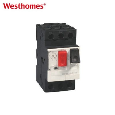
| Industrial Facilities | Motors, machines, heavy loads | MCCB, Motor Protection Devices |
| Data Centers | Continuous loads, redundancy | MCCB, SPD |
| Solar PV Systems | DC output, inverter capacity | DC Circuit Breaker, SPD |
Why Application Context Matters
Understanding the specific load profile of each application ensures the calculated demand reflects real-world operation, not theoretical maximums. This is particularly important for facilities with mixed load types, such as manufacturing plants running motors alongside lighting and HVAC systems.
Standards Related to Electrical Load Calculation
Load calculations should follow applicable electrical standards to achieve safe and reliable system design.
Key IEC and NFPA Standards
| Standard | Description |
|---|---|
| IEC 60364 | Low-voltage electrical installations |
| IEC 60947 | Low-voltage switchgear and controlgear |
| IEC 60898 | Circuit breakers for household applications |
| IEC 61009 | RCBO requirements |
| NFPA 70 (NEC) | Electrical installation requirements |
| NFPA 70E | Electrical safety in workplaces |
Applying Standards in Practice
Following these standards keeps equipment selection, installation, and operation aligned with industry requirements. Local regulations may impose additional or different requirements depending on jurisdiction.
WESTHOMES Circuit Protection Solutions
Accurate load calculation provides the foundation for selecting circuit protection devices. WESTHOMES offers a range of low-voltage protection products designed for different electrical applications.
MCB – Miniature Circuit Breaker
MCBs are commonly used in residential and commercial branch circuits, providing reliable overload and short-circuit protection for lighting circuits, sockets, and small electrical loads.
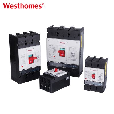
MCCB – Molded Case Circuit Breaker
MCCBs are designed for higher-current applications, including industrial distribution systems and commercial installations. Adjustable protection functions allow flexible application across different load conditions.
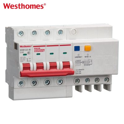
RCBO – Residual Current Circuit Breaker with Overcurrent Protection
RCBO combines overload, short-circuit, and earth leakage protection in one device, suitable for applications requiring enhanced electrical safety.
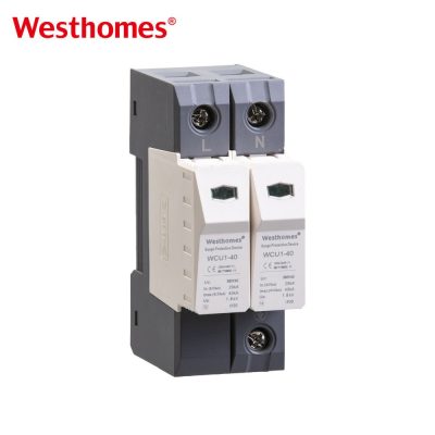
SPD – Surge Protective Device
SPDs protect electrical equipment from transient overvoltage caused by lightning strikes and switching operations, improving system reliability.
Frequently Asked Questions
Conclusion
Electrical load calculation is the foundation of safe and reliable electrical system design. By evaluating connected loads, demand factors, continuous operation requirements, and power characteristics, engineers determine the capacity required for cables, circuit breakers, and distribution equipment.
A sound load calculation goes beyond determining electrical capacity. It prevents overload conditions, improves energy efficiency, supports correct protection coordination, and keeps electrical systems operating reliably throughout their service life. Whether applied in residential buildings, commercial facilities, industrial plants, or renewable energy systems, accurate load calculation is the starting point for selecting the right electrical components. Combined with well-chosen protection devices such as MCBs, MCCBs, RCBOs, and SPDs, it forms the basis of a safer and more stable low-voltage electrical system.

--- END ---
In this blog
Featured Articles
Get A Free Quote