Get quick appointment for technical support!

How an Automatic Transfer Switch (ATS) Works with a Generator
Jun 27, 2026
Introduction
In many facilities, a power outage is not just an inconvenience but a serious operational risk. Hospitals, factories, data centers, and commercial buildings all rely on continuous power to keep critical systems running without interruption.
An automatic transfer switch (ATS) is the key interface between the utility supply and a backup generator. It ensures that when the main power source fails, electrical loads are safely transferred to standby power without manual intervention.
What is an Automatic Transfer Switch (ATS)?
An ATS is an electrically operated switching device that automatically transfers the load between two power sources: the primary utility supply and a standby generator.
Unlike a manual transfer switch, the ATS continuously monitors electrical conditions and reacts instantly when abnormal voltage, frequency drops, or complete power loss is detected.
Its primary function is not to generate power, but to manage where the power comes from. An automatic transfer switch sits between the utility supply and the generator, and its changeover time decides how long the load stays dark.
Core Working Principle of ATS with a Generator
The operation of an automatic transfer switch (ATS) is not a simple switching action, but a coordinated control process that continuously monitors power quality, evaluates system status, and executes a safe transfer between two independent power sources.
At its core, the ATS works as a decision-making device that ensures power is always supplied from the most stable source without overlapping connections between utility and generator.
Operational Logic Sequence
Instead of a single switching action, ATS operation is built on layered control logic involving detection, verification, and execution stages:
1. Continuous power monitoring
The ATS continuously measures voltage, frequency, and phase conditions of the utility supply to ensure it remains within acceptable operating limits.
2. Abnormal condition detection and validation
When voltage drops, phase loss, or complete outage occurs, the ATS does not immediately switch. A built-in delay function validates the fault to avoid unnecessary generator starts caused by transient disturbances.
3. Generator start command activation
Once the fault is confirmed, the ATS sends a dry-contact signal to start the standby generator. This ensures that backup power is only engaged when truly required.
4. Voltage and frequency stabilization check
Before load transfer, the ATS verifies that generator output has stabilized within rated voltage and frequency ranges. This prevents unstable transfer conditions that could damage connected equipment.
5. Load transfer operation (break-before-make)
The ATS disconnects the utility supply first, then connects the generator supply. This “open transition” ensures that the two sources are never connected simultaneously.
6. Return transfer to utility power
When utility power returns and stabilizes, the ATS switches the load back after a confirmation delay and initiates generator cool-down before shutdown.
System Safety Principle
The most critical function of an ATS is preventing backfeed conditions. By ensuring that only one power source is connected at any time, it protects generators, utility lines, and downstream electrical equipment from dangerous reverse power flow.
Step-by-Step Operation Sequence
The operation of an automatic transfer switch (ATS) follows a carefully engineered sequence designed to maintain uninterrupted power delivery while ensuring that two independent power sources are never connected at the same time.
Each stage is controlled by internal logic in the ATS controller, which continuously evaluates power quality and system readiness before executing any switching action.
Normal operating condition (Utility supply mode)
Under normal conditions, the load is supplied directly by the utility grid. The ATS remains in monitoring mode, with internal contacts positioned to maintain a stable connection to the primary source.
During this stage, the generator remains in standby and is not engaged.
Continuous monitoring of electrical parameters
The ATS continuously monitors voltage level, frequency stability, and phase sequence of the incoming utility supply.
If all parameters remain within predefined thresholds, the system remains in normal operation without interruption.
Detection of power failure or abnormal condition
When the system detects undervoltage, overvoltage, phase loss, or complete power failure, the ATS enters a fault recognition stage.
A built-in time delay prevents unnecessary switching caused by short transient disturbances.
Generator start command issuance
Once the fault condition is confirmed, the ATS sends a dry contact signal to the generator control system to initiate startup.
At this stage, the ATS does not yet transfer load; it only prepares backup power availability.
Generator voltage and frequency stabilization
After starting, the generator must reach stable operating conditions before load transfer is allowed.
The ATS continuously checks voltage and frequency to ensure they meet rated specifications.
If instability is detected, transfer is delayed until stabilization is achieved.
Load transfer operation (Open transition switching)
Once the generator is stable, the ATS disconnects the utility supply first, then connects the generator supply.
This “break-before-make” mechanism ensures that there is no electrical overlap between the two sources.
It is the most widely used transfer method in standard backup systems.
Operation under generator supply mode
The load is now fully supplied by the generator. The ATS continues monitoring both generator output and utility supply in parallel.
If the generator becomes unstable, protective logic may initiate alarm or shutdown sequences depending on system design.
Utility power recovery detection
When utility power returns, the ATS does not immediately transfer back. It first verifies that voltage and frequency are stable for a defined period.
This prevents repeated switching during unstable grid recovery conditions.
Return transfer to utility supply
After stability confirmation, the ATS performs a reverse transfer: disconnecting the generator first and reconnecting the utility supply.
A cool-down period is typically applied to the generator before shutdown.
System safety principle
The entire operation is built on one fundamental rule: no parallel connection between utility and generator power sources. This ensures electrical isolation, prevents backfeeding, and protects both upstream and downstream equipment.
Types of ATS Transfer Modes
Automatic transfer switches (ATS) are designed with different transfer modes to meet varying levels of power continuity requirements. The choice of transfer mode directly affects system reliability, cost, switching speed, and protection strategy.
In practical electrical design, selecting the correct transfer mode is as important as selecting the ATS itself.
Open Transition (Break-before-Make)
This is the most widely used ATS transfer mode in standard electrical systems. During transfer, the ATS fully disconnects the primary source before connecting the backup generator.
This ensures complete electrical isolation between the two sources.
Key characteristics:
- Simple and cost-effective design
- No risk of backfeed between sources
- Short interruption during transfer
- Suitable for most commercial and industrial applications
Typical applications:
- Commercial buildings
- Industrial distribution systems
- Standard backup power systems
Closed Transition (Make-before-Break)
Closed transition ATS allows both power sources to be connected in parallel for a very short duration (typically milliseconds) during transfer.
This requires precise synchronization of voltage, frequency, and phase angle between utility and generator.
Key characteristics:
- Near-zero interruption power transfer
- High technical complexity
- Requires synchronization control system
- Higher cost and stricter system requirements
Typical applications:
- Data centers
- Hospitals and critical care facilities
- Mission-critical industrial systems
Delayed Transition
Delayed transition introduces a programmed time delay between disconnection of one source and connection of another. This delay allows residual currents to decay and ensures stable switching conditions, especially for inductive loads.
Key characteristics:
- Prevents electrical stress on sensitive loads
- Reduces inrush and transient currents
- Adjustable delay settings depending on application
- Slightly longer interruption compared to standard open transition
Typical applications:
- Motor-driven systems
- HVAC systems
- Compressor and pump applications
Selection Principle
The selection of ATS transfer mode should be based on system criticality:
- If cost and simplicity are priorities → Open transition
- If zero interruption is required → Closed transition
- If load protection is critical → Delayed transition
In real engineering practice, the final decision often involves balancing system cost, load sensitivity, and operational continuity requirements.
WESTHOMES ATS Product Overview
The WCQ2A series dual power automatic transfer switch is designed for reliable power switching between a normal power supply and a standby (reserve) power source in emergency power systems. It ensures continuous power delivery by automatically transferring loads when abnormal conditions occur on the main supply.
This series is suitable for AC 50Hz/60Hz systems with a rated operational voltage of 400V and a rated current range from 16A to 2000A. It can operate in both automatic and manual modes depending on system requirements.
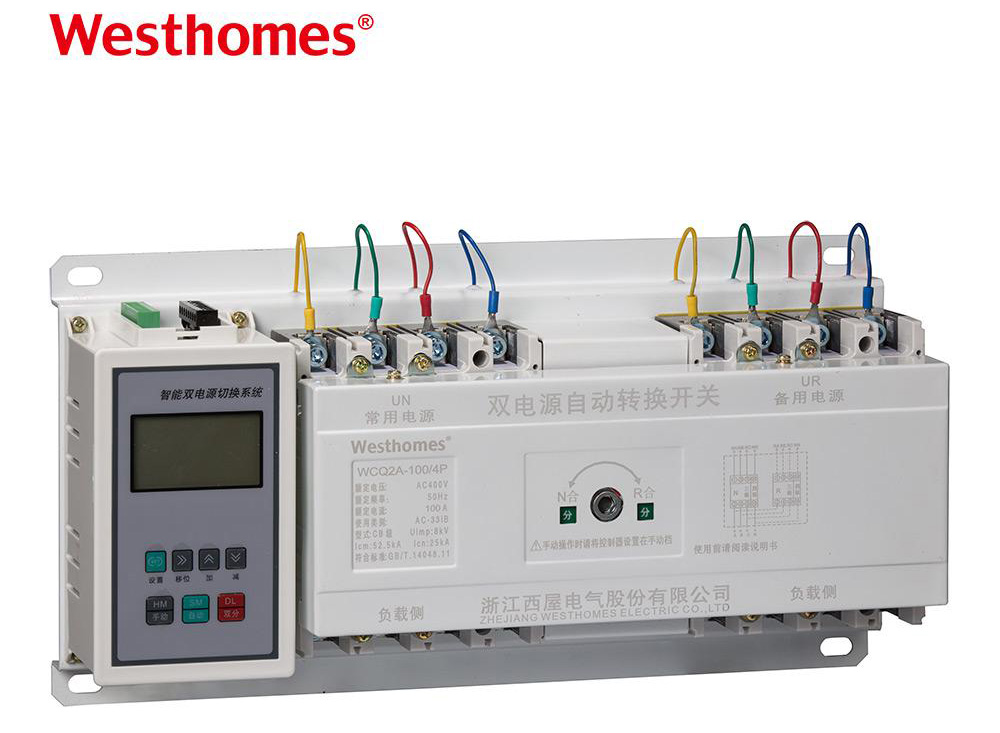
In addition to power transfer functionality, the WCQ2A series also integrates control, signal feedback, and mechanical/electrical interlocking functions, ensuring safe and stable operation in complex electrical systems.
The product is fully compliant with IEC 60947-6-1 standards, making it suitable for industrial, commercial, and infrastructure applications where reliable power continuity is critical. On a single phase installation, two pole changeover for single phase supplies is usually enough, provided the neutral is switched along with the live conductor.
Applications of ATS with Generators
Automatic transfer switches (ATS) are used in any electrical system where power continuity is critical and manual intervention is not fast or reliable enough to ensure safe operation. In modern power systems, ATS devices act as the key interface between utility power and standby generators, ensuring seamless transition during outages.
The importance of ATS becomes even more significant in environments where even a short power interruption can lead to safety risks, production loss, or data corruption.
Hospitals and healthcare systems
In hospitals, uninterrupted power is essential for life-support equipment, surgical systems, ICU units, and emergency lighting. ATS ensures that backup generators are activated within seconds of a power failure, preventing any interruption to critical medical operations.
Without ATS, manual switching delays could directly endanger patient safety.
Data centers and IT infrastructure
Data centers require stable and continuous power to prevent server downtime, data corruption, and network interruption. ATS ensures instant transfer to generator power, maintaining uptime and protecting sensitive digital infrastructure.
Even a few seconds of outage can cause significant data loss or service disruption.
Industrial production facilities
In manufacturing environments, power interruptions can stop production lines, damage partially processed materials, and cause equipment misalignment. ATS ensures continuous operation of critical machinery and reduces production downtime.
Commercial buildings
Commercial buildings such as shopping malls, office towers, and hotels rely on ATS systems to maintain lighting, elevators, security systems, and fire protection systems during outages.
Remote off-grid power systems
In remote or off-grid installations, ATS is often used in hybrid systems combining solar, battery storage, and diesel generators. It manages power source selection automatically based on availability and load demand.
Emergency backup systems
ATS is widely used in emergency backup applications where immediate power restoration is required. These systems are commonly found in fire protection systems, security installations, and critical communication networks.
Common Installation Considerations
Proper installation of an automatic transfer switch (ATS) is essential for safe operation, reliable switching, and long-term system stability. Since the ATS connects utility power and generator systems, installation must follow electrical engineering standards rather than basic wiring practices.
Key Installation Considerations
- System voltage and current matching
The ATS must match the rated voltage, frequency, and current of the electrical system to avoid overheating or insulation stress. - Proper grounding and neutral configuration
Correct grounding ensures safe fault current discharge and stable system operation. Incorrect neutral wiring may cause leakage current or protection failure. - Generator control compatibility
Ensure correct wiring between ATS and generator control terminals, including start/stop signals and feedback signals for reliable communication. - Transfer delay settings
Time delays help avoid unnecessary switching caused by temporary voltage fluctuations and allow generator stabilization before load transfer. - Load type and inrush current consideration
Inductive or motor loads generate high inrush current. ATS settings must be designed to prevent nuisance tripping. - Mechanical installation quality
ATS must be firmly mounted inside a properly ventilated enclosure to prevent vibration, overheating, or terminal loosening. - Environmental protection (IP rating)
Select appropriate enclosure protection level according to humidity, dust, and temperature conditions. - Compliance with electrical standards
Installation must follow IEC or local electrical codes to ensure safety and regulatory approval.
Conclusion
An automatic transfer switch plays a critical role in ensuring uninterrupted power supply when the main grid fails. By intelligently controlling the transfer between utility and generator power, it protects both equipment and operations from unexpected outages.
Understanding how an ATS works helps engineers design safer and more reliable power systems.

--- END ---
In this blog
Featured Articles
Get A Free Quote
