Get quick appointment for technical support!
How do I choose the right molded case circuit breaker for my electrical system?
Jun 24, 2026
Introduction
Selecting the right molded case circuit breaker (MCCB) is essential for safe and reliable electrical system operation. It protects cables, equipment, and personnel from overload and short-circuit faults.
However, MCCB selection is often oversimplified, with many users focusing only on current rating while ignoring key factors such as breaking capacity, load characteristics, and system conditions.
This guide explains the key factors for selecting an MCCB based on real engineering requirements, not just nameplate values.
What is a Molded Case Circuit Breaker (MCCB)?
A molded case circuit breaker (MCCB) is a protective device used to automatically disconnect electrical circuits during overload or short-circuit conditions. It integrates thermal and magnetic protection in a compact design and is commonly used in industrial and commercial power distribution systems.
Key Parameters for MCCB Selection
Selecting a molded case circuit breaker (MCCB) requires evaluating multiple electrical parameters together. Each parameter reflects a different aspect of system performance, including load behavior, fault protection, and installation conditions. Relying on a single specification is not sufficient for proper engineering design.
Rated Current (In)
Rated current defines the maximum continuous current that the MCCB can carry under specified conditions without tripping. It is directly related to the thermal capacity of the device. In practical design, the selected value should always be higher than the calculated load current, but not excessively oversized, as this may reduce protection sensitivity and compromise overload protection performance.
Load current calculation:
Three-phase: IL = P / (√3 × U × cosφ)
Single-phase: IL = P / (U × cosφ)
Selection rule: In ≥ IL × Fmargin, where Fmargin ≈ 1.10–1.25 (or per manufacturer/standard).
Environmental correction: In_required = IL / ktemp × kalt × kgroup, where k_temp, k_alt, k_group are correction factors for temperature, altitude, grouping.
Breaking Capacity (Icu / Ics)
Breaking capacity refers to the maximum short-circuit current that the MCCB can safely interrupt without damage. It represents the device’s ability to withstand and clear fault conditions. This parameter is particularly critical in industrial and commercial systems where prospective fault currents can be extremely high.
Requirement: Icu ≥ Ipros × Fsafety, Fsafety typically 1.0–1.25.
Prospective short-circuit current (simplified): Ik ≈ U / Zth (use line or phase voltage consistently).
Peak versus RMS: Ipeak ≈ √2 × k × Ik_sym, where k (peak factor) ≈ 1.6–2.0 depending on X/R, used to assess instantaneous stresses.
Rated Voltage
The rated voltage must match the system voltage (AC or DC). An incorrect voltage rating may lead to insulation stress, reduced performance, or unsafe operation under fault conditions.
Ensure U_rating ≥ U_system.
Voltage drop check: V_drop = I_load × Z_line, ensure allowed voltage drop limits.
For DC or special systems, confirm DC break rating and arc extinction characteristics.
Number of Poles
The number of poles depends on the system configuration and whether neutral protection is required.
| System Type | Recommended Poles | Application Notes |
| Single-phase | 1P / 2P | Residential or light commercial circuits |
| Three-phase | 3P | Standard industrial power systems |
| Three-phase + Neutral | 4P | Systems requiring neutral isolation or full disconnection |
Trip Unit Type
The trip unit determines how the MCCB responds to overload and short-circuit conditions. Different technologies are used depending on the application requirements.
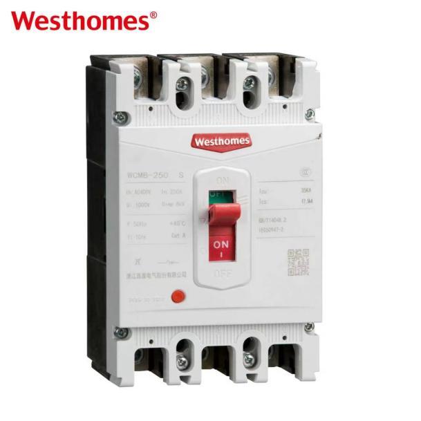
- Thermal-magnetic MCCB: provides standard protection for general electrical distribution systems.
👉 WESTHOMES WCM8series is designed for reliable thermal-magnetic protection in residential, commercial, and light industrial applications, offering stable performance and cost-effective protection.
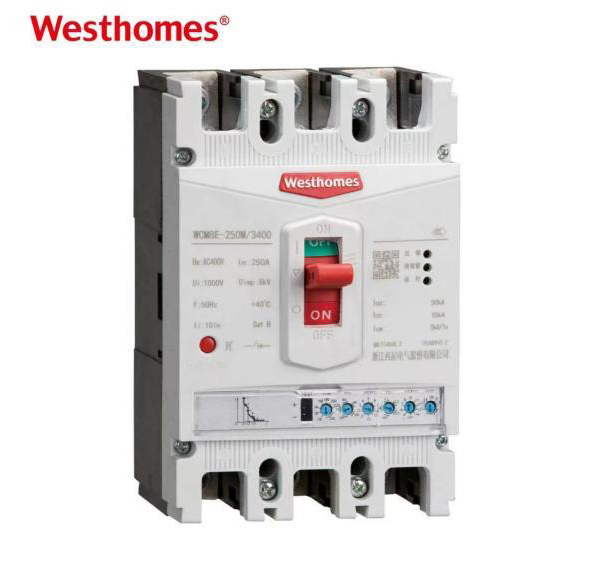
- Electronic MCCB: offers adjustable protection settings, higher accuracy, and advanced fault coordination for complex industrial systems.
👉 WESTHOMES WCM8Eseries adopts electronic trip technology, allowing more precise protection settings and better adaptability in industrial power distribution systems.
Load Type
Different load types directly affect MCCB selection, especially in terms of inrush current and operating stability.
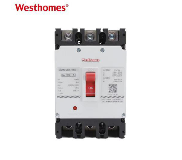
- Resistive loads: stable current with minimal fluctuation (e.g., heating, lighting systems)
👉 WESTHOMES WCM5series is suitable for resistive load applications where current behavior is stable and predictable.
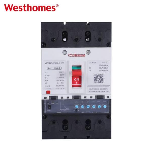
- Mixed loads: combination of resistive and inductive characteristics commonly found in industrial environments
👉 WESTHOMES WCM5Exseries is designed for mixed load conditions, providing improved adaptability for systems with variable electrical behavior such as machinery, production lines, and general industrial installations.
- Inductive loads: high inrush current during startup (motors, compressors, transformers)
MCCB Selection Based on System Conditions
MCCB selection should always be based on real system conditions rather than theoretical values alone. In practical engineering, factors such as load behavior, short-circuit level, installation environment, and system expansion must all be considered to ensure safe and reliable operation.
A structured, condition-based approach helps avoid undersized or oversized selection and improves overall system coordination.
Step 1: Analyze total load current
The first step is to determine the total operating current of the system under normal working conditions. This includes all connected loads and expected continuous operation demand.
This value forms the baseline for MCCB rated current selection.
Step 2: Evaluate load characteristics
Different load types behave differently under operation. Resistive loads are stable, while inductive loads introduce higher inrush current and transient variations.
Understanding load behavior is essential to prevent nuisance tripping and ensure proper protection coordination.
Step 3: Determine system short-circuit level
The prospective fault current at the installation point must be evaluated before selecting the MCCB. The breaking capacity (Icu / Ics) of the device must be higher than the calculated fault level.
Failure to meet this requirement may result in device damage during fault conditions.
Step 4: Apply safety margin to load current
Engineering practice typically applies a safety factor (commonly 1.25×) to account for load variation, temperature effects, and future uncertainty.
Step 5: Check installation environment
Environmental conditions such as ambient temperature, enclosure ventilation, and altitude can significantly affect MCCB performance. High-temperature environments may require derating adjustments.
Step 6: Ensure cable and system coordination
The MCCB must always be coordinated with cable ampacity to ensure that the protection device trips before the cable reaches thermal limits. Improper coordination may lead to overheating or fire hazards.
Step 7: Select standard MCCB frame size
After all calculations, select an MCCB from the manufacturer’s standard frame range that best matches the required current rating, breaking capacity, and application type.
Common Mistakes in MCCB Selection
In practical electrical design, incorrect MCCB selection is a frequent cause of system instability, reduced protection performance, and premature equipment failure. These mistakes often come from simplifying engineering requirements or misunderstanding the role of protection devices in system coordination.
Below are the most common issues encountered in real-world applications, along with their technical implications.
Selecting MCCB based only on current rating
This is one of the most common mistakes. While rated current is important, it does not reflect fault level, load type, or system coordination requirements. Relying only on current rating may result in unsafe or unbalanced protection design.
Ignoring short-circuit breaking capacity (Icu / Ics)
The breaking capacity defines the MCCB’s ability to safely interrupt fault currents. If this parameter is ignored, the device may fail catastrophically during short-circuit conditions, leading to severe equipment damage and safety hazards.
Oversizing “for extra safety margin”
Increasing the MCCB rating without proper calculation may reduce nuisance tripping, but it also reduces overload protection sensitivity. This can leave cables and downstream equipment exposed to thermal stress during abnormal conditions.
Ignoring temperature derating factors
MCCBs are affected by ambient temperature. In high-temperature environments such as industrial cabinets, failure to apply derating factors may result in inaccurate protection performance and overheating risks.
Mismatching MCCB with cable size and system coordination
Proper coordination between MCCB and cable ampacity is essential. If the MCCB is oversized relative to the cable, the cable may overheat before the breaker trips, creating a serious fire hazard.
Application Scenarios
Molded case circuit breakers (MCCBs) are widely used in low-voltage electrical systems where reliable overload and short-circuit protection is required. Their ability to handle a wide current range and high fault levels makes them suitable for both industrial and commercial power distribution applications.
Rather than being limited to a single function, MCCBs are typically integrated into different system layers, from incoming power protection to final equipment-level safeguarding.
Power distribution systems
In main and sub-distribution boards, MCCBs are used to protect outgoing feeders and ensure safe isolation of circuits during maintenance or fault conditions. They form the backbone of low-voltage distribution protection.
Industrial control panels
MCCBs are commonly installed in industrial control panels to protect automation systems, control circuits, and power supply lines from overload and short-circuit events.
Motor protection circuits
Motors generate high inrush current during startup, making MCCBs essential for providing both thermal protection and short-circuit protection in motor feeder circuits.
HVAC systems
In HVAC applications, MCCBs provide reliable switching and protection for compressors, fans, and pumps, ensuring stable operation under varying load conditions.
Renewable energy systems
MCCBs are widely used in solar PV and energy storage systems to protect DC/AC circuits, ensuring safe disconnection during maintenance and fault conditions.
Generator switching systems
In backup and standby generator systems, MCCBs are used for safe switching between utility power and generator supply, ensuring uninterrupted and controlled power transfer.
Frequently Asked Questions (FAQ)
Q1 How do I choose the correct MCCB current rating?
The MCCB current rating should be based on the calculated load current, with an appropriate safety margin (typically 1.25×). It should not be oversized excessively, as this may reduce overload protection sensitivity.
Q2 What is the difference between Icu and Ics in MCCB?
Icu represents the ultimate breaking capacity, while Ics represents the service breaking capacity. Ics indicates the level at which the MCCB can continue to operate safely after interrupting a fault.
Q3 Can I use a higher MCCB rating for better safety?
Not necessarily. Oversizing the MCCB may prevent nuisance tripping, but it can also reduce protection effectiveness, allowing cables or equipment to overheat under fault conditions.
Q4 How important is breaking capacity in MCCB selection?
Breaking capacity is critical because it determines whether the MCCB can safely interrupt a short-circuit current. It must always be higher than the system’s prospective fault level.
Q5 Do environmental conditions affect MCCB performance?
Yes. High ambient temperature, poor ventilation, and enclosed installation conditions can reduce the MCCB’s effective current-carrying capacity. Derating may be required.
Q6 What happens if MCCB is undersized?
An undersized MCCB may trip frequently during normal operation, causing system instability and unnecessary downtime.
Conclusion
Choosing the right MCCB requires more than selecting a current rating. A proper selection must consider load characteristics, fault level, installation environment, and system coordination.
A correctly selected MCCB improves system reliability, reduces downtime, and ensures long-term electrical safety.

--- END ---
Prev: ACB vs MCCB: When to Specify an Air Circuit Breaker
Already the latest article
In this blog
Featured Articles
Get A Free Quote