Get quick appointment for technical support!
ACB vs MCCB: When to Specify an Air Circuit Breaker
Jun 21, 2026
When should I use an air circuit breaker instead of MCCB? It’s the kind of question that surfaces early in a project and tends to get answered too quickly. You’re designing the main incomer for a 3,000A low-voltage distribution board at a large industrial plant.
Your equipment schedule lists both a high-frame MCCB and an ACB as candidate devices at roughly the same ampacity. The catalog specs overlap, the datasheets look similar, and the pricing difference feels substantial. Specifying the wrong device doesn’t just waste money, it creates protection coordination failures, maintenance headaches, and costly rework that your project can’t absorb.
The problem isn’t a lack of options. Manufacturers like Westhomes, who build both ACBs and MCCBs across a full range of frame sizes, design each device family for fundamentally different duties within the same distribution system.
The overlap in ratings is real, but the design intent behind each device is not interchangeable. What follows is the exact sequence of thresholds engineers use to resolve the air circuit breaker vs. MCCB decision in the field.
When Should I Use an Air Circuit Breaker Instead of MCCB: Current Rating and Ampacity
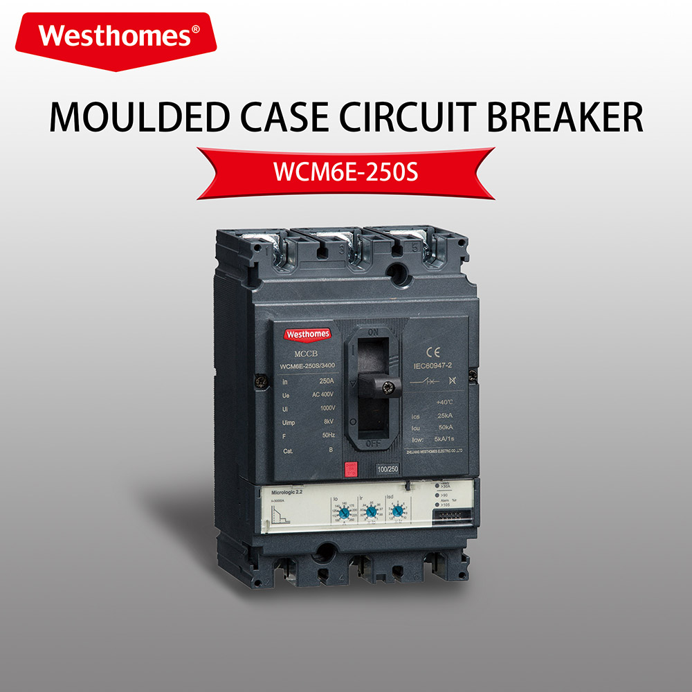
Both device types occupy an overlapping ampacity band from roughly 400A to 2,500A, which is precisely where most specification errors happen. An MCCB is available in frames up to 3,200A, and ACBs begin at around 400A, so on paper both devices exist in the middle of that range.
The real question isn’t which device is available at a given rating, it’s which device is designed for sustained operation at that rating under the thermal and mechanical stress of a main incomer position.
ACBs are built for continuous high-current duty. Their open construction, large contact surfaces, and arc chutes dissipate heat more effectively than a molded case at the same rating.
For systems where the main incomer routinely operates at or near full rated current (think large industrial drive loads, data center PDUs, or main switchboards in commercial towers), an ACB’s derating behavior is far more predictable than a thermally sensitive MCCB frame. Once continuous load demand exceeds 1,600A to 2,000A, the ACB becomes the practical default even before fault current enters the calculation.
Breaking Capacity and Short-Time Withstand: The Fault-Level Threshold
Ultimate breaking capacity (Icu) gets compared first in most spec reviews, but it’s the service breaking capacity (Ics) that governs real-world air circuit breaker selection.
A large-frame MCCB may publish an Icu of 100 kA at 480V, but its Ics, the rating it can deliver repeatedly without degradation, may be only 25% to 50% of that figure. For a main incomer expected to clear fault current multiple times over its service life, specifying to Icu alone is a false economy. For a simple primer on the difference between these ratings see Ics and Icu explained.
Icu vs. Ics: Why Service Rating Matters More
For critical applications with high uptime requirements, data centers, hospitals, and large industrial facilities, Ics should reach 75% to 100% of the available fault current. At 100% Ics, most MCCB frames can’t match what ACBs deliver as a standard specification.
This is where the Icu comparison becomes misleading: a high-end MCCB may reach 150 kA Icu on paper, but its practical Ics at the main bus fault level is what actually determines long-term reliability.
Icw: The Defining Differentiator Between Device Families
The short-time withstand current (Icw) is the single most important differentiator between these two device families. An ACB can hold a fault current, typically 50 kA to 150 kA, for up to one full second without tripping, which is what makes intentional time-delay selectivity possible at the system level.
Thermal-magnetic MCCBs carry no Icw rating at all; they trip as soon as fault current appears. Electronic MCCBs offer limited Icw, often 25 to 50 kA for 0.1 seconds. For a deeper look at short-time and ICW rating behavior see this technical note on Icw rating explained.
Once your system’s available fault current exceeds roughly 50 kA at the main bus, or once selective coordination requires a timed upstream response, an ACB is the technically correct choice, not just a larger MCCB.
Per IEC 60947-2 guidance, which governs low-voltage switchgear breakers including both ACBs and MCCBs, the Icw requirement for the main incomer position should be evaluated against the prospective fault current at the point of installation, not a conservative estimate.
Selectivity and Time-Current Coordination in Tiered Distribution
In a properly coordinated system, the downstream MCCB should clear faults within its zone before the upstream ACB commits to tripping. Achieving this requires the ACB’s time-current characteristic to sit consistently above and to the right of the MCCB curve across the full range of expected fault current.
For ACBs with electronic trip units, this is accomplished by programming a short-time delay, typically 100ms to 400ms, long enough to allow the downstream device to clear but short enough to prevent equipment damage.
Setting the short-time delay follows a specific workflow. Start with the downstream MCCB settings as low and fast as practical for the load profile, then calibrate the upstream ACB’s long-time and short-time bands around those settings.
The ACB’s Icw rating must cover the full fault current during that delay window, which is exactly why a high Icw matters operationally and not just on a spec sheet.
Coordination isn’t confirmed by visual curve comparison alone. At high fault currents, time-current curves can appear separated in the overload region but overlap critically in the instantaneous region. The only reliable method is cross-referencing the manufacturer’s tested coordination tables for the specific ACB and MCCB pair at the available fault current. For guidance on field best practices see this article on selective coordination best practices.
Ground-fault settings require a separate check. Phase-curve coordination can look clean while ground-fault curves still overlap, and missing that creates a gap in the protection scheme that won’t surface until a fault event exposes it.
Control Features, Installation, and Lifecycle Cost
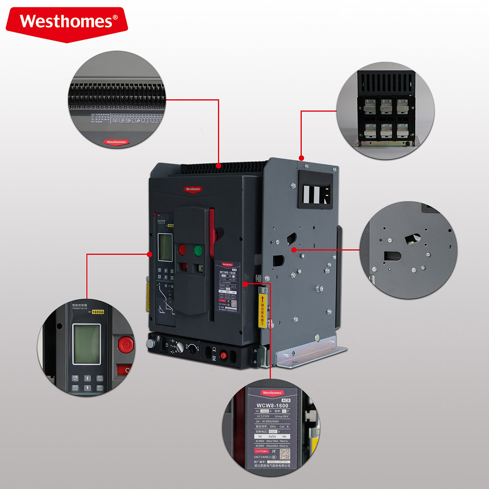
ACBs are built around a draw-out chassis and modular architecture that supports motorized closing, remote trip and close signals, position feedback, and interlocking with other switchgear. These features aren’t accessories in most ACB designs, they’re integral to how the device is specified for automated or remotely monitored distribution systems.
For any main incomer in a facility with a building management system, SCADA integration, or an automatic transfer scheme, the ACB’s control architecture delivers functional advantages that molded-case configurations can’t match natively.
MCCBs can be configured with motorized operators, but this typically must be specified at order time, and the control integration is less comprehensive than what ACBs provide as standard. For a straight forward feeder circuit that needs no remote operation, this distinction doesn’t matter. For a main incomer in a critical facility, it absolutely does.
On size and weight: a 2,000A ACB with its draw-out cradle typically runs 85 to 100 kg and requires panel depth exceeding 600mm to accommodate pull-out clearance. A 2,000A MCCB runs 25 to 40 kg and fits in panels with 350 to 400mm depth. These differences directly affect panel layout, structural load calculations, and switchboard design.
Maintenance is more involved for ACBs: arc chutes need periodic inspection, contacts require replacement at defined cycle counts, and the draw-out mechanism requires lubrication and operational checks on a scheduled basis. That serviceability is also the ACB’s lifecycle advantage, components are replaceable without swapping the entire device.
Over a 10 to 15-year service life, a well-maintained ACB in a main incomer position typically carries lower total cost than repeated MCCB replacement under high fault-duty conditions. For a current market reference on comparative costs see the 2026 MCB, MCCB & ACB Price Guide & Costs published by Westhomes.
Real-World Scenarios That Call for an ACB
In a steel plant or large manufacturing facility, the main LV distribution board typically receives power from a 2,000 kVA to 5,000 kVA transformer (per IEC 60947 sizing conventions). Available fault current at the main bus frequently exceeds 50 kA to 85 kA. That fault level, combined with continuous loads well above 1,600A, puts the main incomer firmly in ACB territory.
The downstream MCCBs protecting individual feeder circuits remain the correct choice for their zones: smaller, faster, and more economical at lower ampacity levels. The same logic applies to large commercial buildings, where the main incomer ACB handles high fault duty and coordinates with MCCB feeders serving floor-by-floor sub-boards.
In critical facilities, the stakes are higher. A single nuisance trip at the main incomer in a data center or hospital can cascade into a full facility outage. An ACB with a programmed short-time delay absorbs the fault current long enough for the downstream MCCB to clear the affected circuit, keeping the rest of the system energized.
This is where Icw ratings move from a technical specification to an operational requirement: specifying anything less at the main incomer of a data center or hospital distribution board is a design risk that no project owner should accept.
One procurement consideration engineers often underestimate is the coordination data gap between ACB and MCCB brands. Manufacturer-tested coordination tables are device-pair specific. A table verified for one brand’s ACB with that brand’s MCCB may not apply when devices are mixed across suppliers.
Sourcing both the main incomer ACB and downstream MCCBs from a single manufacturer that publishes matched coordination data eliminates this uncertainty entirely.
Westhomes’ ACB product range covers both ACBs and MCCBs across a full range of frame sizes, with consistent certification documentation covering CE, CB, and TÜV alongside additional international standards.
See, for example, the Intelligent Universal Circuit Breaker 630A 3p/4p for a typical modular, certified ACB offering. For procurement teams navigating multi-tier distribution systems, that single- source model means verified coordination tables, unified technical support, and no gaps between device families, without chasing documentation across multiple vendors.
Making the Final Call on Air Circuit Breaker vs. MCCB Selection
So when should you use an air circuit breaker instead of an MCCB? The answer follows three thresholds, evaluated in order. Use an MCCB for feeders and sub-distribution where continuous loads stay below 1,600A and available fault current is manageable within the device’s Ics rating.
Specify an ACB when continuous ampacity exceeds 1,600A to 2,000A, when available fault current at the main bus approaches or exceeds 50 kA, or when selective coordination requires a timed upstream response that depends on a declared Icw.
The ACB’s higher upfront cost and larger physical footprint are justified by the performance obligations of the main incomer position, obligations that a molded-case device isn’t built to fulfill at that level. For the specification and procurement process, matching your ACB and MCCB selection to a manufacturer whose coordination data covers both device families makes the spec process faster and the final design more defensible.
If you’re sourcing both device types for a distribution system and need technical documentation, coordination tables, or OEM support, Westhomes is built to support exactly that workflow, from single-project procurement to scalable distribution supply.
| Air Circuit Breaker(ACB)vs Molded Case Circuit Breaker(MCCB)Comparison | ||
| Comparison Item | Air Circuit Breaker(ACB) | Molded Case Circuit Breaker (MCCB) |
| Core Design Intent | Engineered for continuous high-current duty in main incomer positions, designed to handle sustained thermal and mechanical stress at full rated current |
Designed for feeder and sub-distribution circuits, optimized for lower ampacity, fast fault clearing in downstream zones |
| Current Rating &Ampacity Range | Starts from~400A, with practical default for continuous loads exceeding 1600A-2000A; built for sustained operation at full rated current |
Available up to 3200A frame size, but optimal for continuous loads below 1600A; thermally sensitive at higher sustained loads |
| Continuous Operation Performance | Open construction, large contact surfaces, and arc chutes dissipate heat more effectively; predictable derating behavior even at near-fullrated current |
Molded case construction has limited heat dissipation; derating is less predictable under sustained high-current operation |
| Breaking Capacity (lcu&Ics) | Standard Ics rating reaches 75%-100%of available fault current; Ics is aligned with real-world repeated fault clearing requirements | High lcu rating may be published, but practical Ics is typically only 25%-50%of lcu; cannot match ACB’s standard Ics performance at main bus fault levels |
| Short-Time Withstand Current (lcw) | Can hold fault current (typically 50kA-150kA)for up to 1 full second without tripping; enables intentional time-delay selectivity at system level |
Thermal-magnetic MCCBs have nolcw rating(trip immediately on fault);electronic MCCBs offer limited lcw(25-50kA for 0.1 seconds only) |
| Selectivity &Time-Current Coordination | Supports programmable short-time delay(100ms-400ms)via electronic trip units; time-current curve can be calibrated to sit above downstream MCCB curves for full selectivity |
No built-in short-time delay capability; curve overlap with upstream devices is common at high fault currents, risking loss of selectivity |
| Control &Integration Features | Draw-out chassis with modular architecture; motorized closing, remote trip/close signals, position feedback, and interlocking are standard integral features; natively supports BMS/SCADA/ATS integration |
Motorized operators are optional and must be specified at order time; control integration is less comprehensive than ACB; no native support for advanced system integraton |
| Physical Size &Installation Requirements | Larger and heavier;2000A ACB with draw-out cradle weighs 85- 100kg, requires panel depth>600mm for pull-out clearance |
Compact and lightweight;2000A MCCB weighs 25-40kg, fits in panels with 350-400mm depth |
| Maintenance &Lifecycle Cost | More involved scheduled maintenance(arc chute inspection, contact replacement,draw-out mechanism lubrication); all components are replaceable without full device swap; lower total cost over 10-15 year servicelife in high fault-duty conditions |
Minimal maintenance required; no user-serviceable internal components; full device replacement is required after fault events; higher lifecycle cost in high-duty main incomer applications |
| Typical Application Scenarios | Main incomer positions in large industrial plants, data centers, hospitals, commercial towers; systems with available fault currentt >50kA at main bus;applications requiring high uptime and selective coordination |
Downstream feeder circuits,sub-distribution boards,floor-by-floor sub-boards; applications with continuous loads<1600A and manageable fault current levels |

--- END ---
In this blog
Featured Articles
Get A Free Quote