Get quick appointment for technical support!

Motor Protector or Thermal Overload Relay
Sep 24, 2026
Two devices protect a motor, and they are often treated as interchangeable when they are not. One follows the current and models the heat inside the winding. The other does that and adds a magnetic element that responds to a fault current almost instantly. Choosing between them is a question about the circuit rather than about the motor.
This guide compares the two on what they measure, then works through four motor circuits and names the device each one needs.
What Each Device Actually Measures
A thermal overload relay measures current and converts it into a model of winding temperature. The conversion takes time, which is why the relay holds through a start and reacts to a sustained overload. It has no element that responds to a short-circuit fault current.
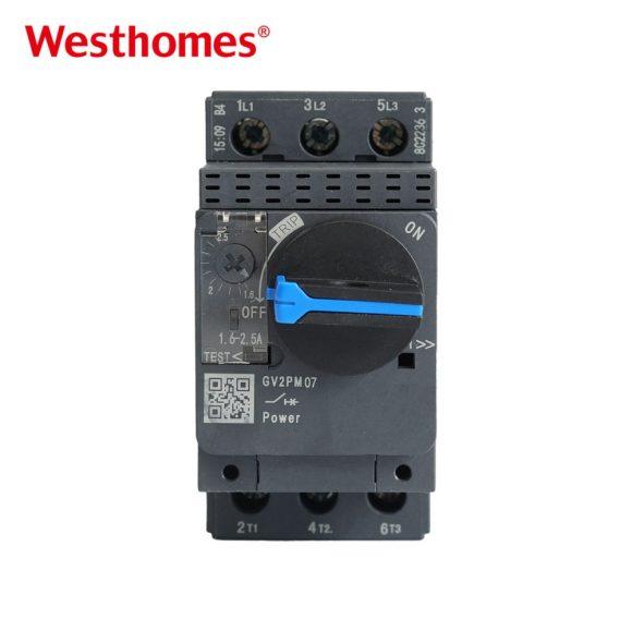
A motor protector carries both a thermal element and a magnetic one. The thermal element behaves like the relay. The magnetic element responds to a current many times the setting within a cycle or two, which is the behavior of a short-circuit rather than an overload.
The published motor protector range covers 0.1 A to 32 A in closely spaced steps, with each step listing a thermal setting range and a magnetic trip current. The range and the protector types are listed under motor protector with the motor power each step suits.
Where the Two Overlap
Both devices protect against overload, and both are set from the motor current. On a circuit where the short-circuit is already handled by something upstream, the two do the same job and the relay is the cheaper answer.
The overlap is what makes the choice confusing. A relay behind a set of fuses has short-circuit protection available, and the relay adds the overload protection. A protector used in the same position duplicates nothing and adds the magnetic trip at the motor rather than at the panel.
The Comparison in One Table
| Question | Thermal Overload Relay | Motor Protector |
| Responds to overload | Yes, after a time delay | Yes, after a time delay |
| Responds to short-circuit | No | Yes, magnetically and fast |
| Setting basis | Motor current | Motor current plus a magnetic threshold |
| Typical mounting | Under a contactor | At the motor or in a starter |
| Reset after trip | Manual or automatic | Manual, with a trip indicator |
| Protects against phase loss | Partly, through the current rise | Partly, through the current rise |
| Range covered here | 0.1 A to 140 A | 0.1 A to 32 A |
| Cost | Lower | Higher |
The two rows that decide most selections are the short-circuit response and the mounting position. Everything else follows from where the device sits in the circuit.
Four Circuits and the Device Each Needs
The cases below cover most motor installations. Each one is decided by what already exists upstream rather than by the motor itself.
A Motor Behind a Distribution Board
A motor fed from a board with its own protective device has short-circuit protection already. The relay sits under the switch that carries the motor current and adds the overload protection. This is the arrangement most panels use, and it is the cheaper one.
A Motor Fed Directly From a Busbar
A motor tapped off a busbar without an individual protective device has nothing to clear a short-circuit at the motor. A protector covers both the overload and the fault, which is why it appears on this arrangement rather than a relay. The magnetic element is what makes the difference.
A Motor Remote From Its Panel
A motor at the far end of a long cable has a short-circuit current limited by the cable. A protector at the motor sees that reduced fault current and still trips, while a device at the panel may not see it at all. Placing the protection at the motor is the reason protectors exist in this form.
A Motor With a Frequent Start
A motor started many times an hour needs a device whose thermal model recovers between starts. Both devices do this, and the faster recovery version is worth specifying where the starts come close together.
Magnetic Trip Setting and Why It Matters Here
The magnetic trip sits above the thermal setting by a published multiple, and the multiple is what makes a protector usable on a motor. A motor draws several times its rated current during a start, and a magnetic element set too low would trip on that start.
The published figures for this range show a magnetic trip current that rises with the frame, from a few amps on the smallest step to several hundred on the largest. Each step is chosen so that the magnetic threshold clears a start and still responds to a fault.
Where the motor is started with a star-delta starter or a soft starter, the starting current is lower and the magnetic setting has more room. Where the motor is started direct on line, the setting has to clear the full start current.
The Decision Comes Down to Four Questions
- Is there already a protective device between the motor and the supply that clears a short-circuit?
- Does the motor sit far enough from its panel that a cable limited fault current would be missed upstream?
- Is the protection to be at the motor rather than in the panel?
- Does the installation need a trip indicator at the machine rather than at the board?
A yes to the first and a no to the other three points at a relay. A no to the first, or a yes to either of the others, points at a protector. The motor rating only enters the decision after that, when the step is chosen.
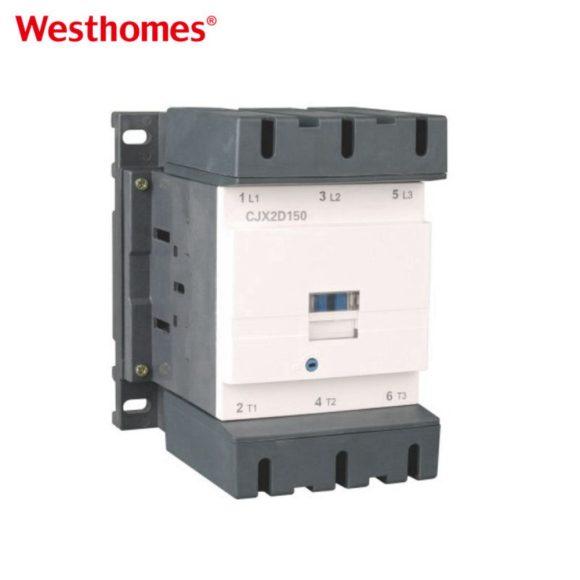
The relay range and the frames it pairs with are listed under thermal overload relay, and the contactor that carries either device is listed under three pole AC contactor.
Final Notes
The two devices share the overload function and differ on everything else, which is why the circuit decides rather than the motor. Look at what already sits between the motor and its supply before looking at the motor rating. Where a fault current at the motor would be limited by cable, having the protection at the motor is worth more than an extra frame size on a device at the panel. And whichever device is fitted, the setting is read from the motor current rather than from the device label.

--- END ---
In this blog
Featured Articles
Get A Free Quote
