Get quick appointment for technical support!

Get in Touch

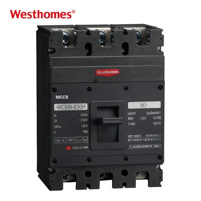
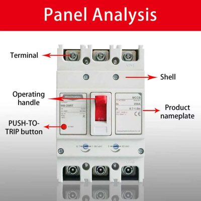
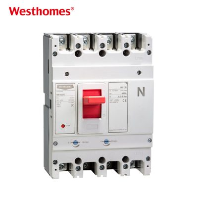
WCM8E-630M AC400V/690V 4 Pole MCCB

The WCM8E-630M 4 Pole Molded Case Circuit Breaker (MCCB) is a high-capacity, AC 400V/690V circuit protection device designed for demanding industrial applications.

Social focus:

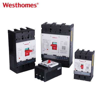
3 Pole 400A MCCB | WCM8E-250M CE/CB Certified Molded Case Circuit Breaker

Engineered with advanced international manufacturing standards, the WCM8E-630M MCCB offers reliable overload, short circuit, and under-voltage protection for large-scale electrical systems.

WCM8E-125M

The WCM8E-630M also supports infrequent switching and motor starting on AC 50Hz systems, and is classified into Type C, L, M, and H based on its rated short-circuit breaking capacity (Icu). Compact in design yet powerful in performance, it offers excellent vibration resistance, zero-flashover design (in certain parts), and versatile mounting options—vertical and horizontal.

Featuring a rated insulation voltage of 800V and an operating voltage range up to 690V, this 4P MCCB is ideally suited for three-phase four-wire systems, ensuring complete circuit isolation and operational safety.

With its 4-pole structure, it provides full protection for all active conductors, including neutral, making it a preferred choice for industrial automation, commercial power distribution, and energy infrastructure.


KEY INFORMATION

Model Frame level rated current (A) Current Rating (A) Rated operation voltage (V) Rated insulation voltage (V) Rated ultimate short circuit breaking capacity (kA) 400V Rated operation short circuit breaking capacity (kA) 400V
WCM8-63L 63 (6), 10, 16, 20, 25, 32, 40, 50, 63 AC400 AC500 25 18
WCM8-63M 50 35
WCM8-125C 100 (10), 16, 20, 25, 32, 40, 50, 63, 80, 100 AC690 AC800 20 10
WCM8-125L 35 17.5
WCM8-125M 50 35
WCM8-125H 85 50
WCM8-250L 225 100, 125, 140, 160, 180, 200, 225 AC690 AC800 35 18
WCM8-250M 50 35
WCM8-250H 85 50
WCM8-400L 400 225, 250, 315, 350, 400 AC690 AC800 50 25
WCM8-400M 65 42
WCM8-400H 100 65
WCM8-630L 630 400, 500, 630 AC690 AC800 50 25
WCM8-630M 65 42
WCM8-630H 100 65
WCM8-800M 800 630, 700, 800 AC690 AC800 75 50
WCM1-800H 100 65
WCM8-1250 800 1000, 1250 AC690 AC800 65 40
WCM8-2000 1250 1400, 1600, 1800, 2000 AC690 AC800 65 40
Description Specification
Frame level rated current Inm(A) 63 125 250 400 630 800 1250
Breaking the capacity level L M C L M H L M H L M H L M H M H
Overall Dimensions
(mm)
Overall Dimensions
W 75/103 65/93/107 74.5/107/142 150/198;定140/184 182/238 210/280 210/280
L 136 150 165 257;定257 270 280 466
H 66.5 61 79 81 99 102;定108 105.5 107.5 139
H1 90.5 86 104 110 127 151.5;定146 155 155 190
Mounting Dimensions
(mm)
Mounting Dimensions
A 25 30 35 44/90;定44/88 58 70 70
B 115 130.5 126 194;定215 200 243 300
Φd 3.5 4.5 5 7;定6.5 7 7 9.5

Basic Info.

Model NO. WCM8E-630M
Arc-extinguishing Medium Air
Structure MCCB
Type Circuit Breaker
Certification ISO9001-2000, CE, CB, CCC
Factory Own
Payment L/C, T/T, D/P, Western Union, Paypal, Money Gram
Specification 10A-800A
Origin China
Production Capacity 5000PCS/Week
Speed High-Speed Circuit Breaker
Installation Fixed
Poles Number 3p, 4p
Function Conventional Circuit Breaker,
Circuit-Breaker Failure Protection,
Overcurrent Protection,
OVP(Overvoltage Protection)
Production Line 100% Automic
Cooperation Type OEM ODM
Transport Package Paper Box
Trademark Westhomes
HS Code 8536200000

FREQUENTLY ASKED QUESTION (FAQ)

What is the WCM8E-630M 4-pole MCCB? plus-square Created with Sketch Beta. minus-square Created with Sketch Beta.

The WCM8E-630M is a 630 A frame, four-pole molded case circuit breaker with an electronic trip unit, rated for AC 400 V and 690 V systems. It is a heavy-duty device used as a main or large feeder breaker in industrial switchgear, commercial substations, and infrastructure projects where high fault currents and precise selectivity are required.

What does "4 Pole" mean and why is it important? plus-square Created with Sketch Beta. minus-square Created with Sketch Beta.

A 4P breaker switches all three phases plus the neutral conductor. This provides full isolation of the downstream circuit, including neutral, which is essential for maintenance safety, for changeover between two power sources, and in installations where neutral voltage displacement could otherwise energize disconnected equipment. It is the standard choice for main incomers in many commercial and industrial boards.

How does the electronic trip unit (E) differ from thermal-magnetic? plus-square Created with Sketch Beta. minus-square Created with Sketch Beta.

The electronic trip unit uses current transformers and microelectronics to measure current and apply accurately set L (long-time), S (short-time), I (instantaneous), and often G (ground-fault) protection curves. This gives far more precise and repeatable settings than a bimetal/electromagnet design, and supports selectivity studies, load monitoring, and communication options on advanced models.

What does the 630 A frame cover in terms of rated current? plus-square Created with Sketch Beta. minus-square Created with Sketch Beta.

The 630 A frame typically accepts trip units from, for example, 250 A up to 630 A. This means one physical breaker can be re-rated by changing the plug-in trip unit as the installation load grows, reducing spare-parts inventory and future upgrade cost.

What does the 400 V/690 V dual rating mean for breaking capacity? plus-square Created with Sketch Beta. minus-square Created with Sketch Beta.

The breaker is certified for use on both 400 V and 690 V AC systems. However, the breaking capacity (Icu/Ics) is voltage-dependent — it is highest at 400 V and typically lower at 690 V. Always consult the manufacturer's rating plate to confirm the breaking capacity at the actual system voltage before installation.

How do I adjust the long-time, short-time, and instantaneous settings? plus-square Created with Sketch Beta. minus-square Created with Sketch Beta.

The long-time pickup (Ir) is set to match the cable ampacity and load full-load current; the short-time pickup (Isd) and delay (tsd) are set to coordinate with downstream feeders; the instantaneous pickup (Ii) is set above maximum inrush but below the downstream device's let-through. Ground-fault (Ig) settings, if fitted, are set below the system's capacitance and surge levels to avoid nuisance trips.

How does this MCCB differ from an MCB? plus-square Created with Sketch Beta. minus-square Created with Sketch Beta.

An MCB is a small, fixed-trip DIN-rail device up to about 125 A with limited breaking capacity, while the WCM8E-630M is a 630 A, panel-mounted, electronically adjustable breaker with breaking capacities commonly from 35 kA to 65 kA or more. MCCBs are used as main and feeder breakers; MCBs protect final circuits downstream.

How is the WCM8E-630M installed and wired? plus-square Created with Sketch Beta. minus-square Created with Sketch Beta.

It is bolt-mounted on a chassis or mounting plate in a low-voltage switchboard. Connections are typically made with laminated copper busbars or multiple large parallel cables (e.g., 2 × 240 mm² copper per pole) using manufacturer-specified lugs and torque. Adequate clearance, ventilation, and access for operation and testing must be built into the cubicle per IEC 60947-2.

What are typical applications for a 630 A 4P MCCB? plus-square Created with Sketch Beta. minus-square Created with Sketch Beta.

Typical uses include main incomers in commercial and industrial substations, large distribution board feeders, data center and hospital switchboards, main protection for large HVAC plants, generator and transformer secondaries, and switchgear for manufacturing plants. The 4P configuration is preferred where neutral isolation or source changeover is required.

What standards govern it, and what maintenance and testing are required? plus-square Created with Sketch Beta. minus-square Created with Sketch Beta.

It is designed and certified to IEC 60947-2 and carries CE and other regional marks. Maintenance should include annual visual inspection, terminal torque verification, mechanical operation exercises, and insulation resistance testing; the electronic trip unit should be verified by secondary injection test every 1–3 years to confirm that L, S, I, and (if fitted) G elements still trip at the set values.

RELATED PROJECTS

REQUEST
YOUR FREE QUOTE

* indicates a required field