Get quick appointment for technical support!

What Does an MCCB Do? Functions in Modern Low-Voltage Distribution
Oct 17, 2026
A miniature circuit breaker protects final circuits, but once a feeder carries hundreds of amps and the available fault current climbs past what that MCB can interrupt, the job moves to a molded case circuit breaker, or MCCB. The MCCB sits between the small breakers on branch circuits and the big air circuit breaker at the main bus, and it does more than trip.

What an MCCB actually is
An MCCB is a circuit breaker housed in a single molded insulating case. Inside, a trip unit releases the mechanism and opens the contacts when current leaves the allowed range. Compared with an MCB, it handles higher current, offers a larger breaking capacity, and usually lets you adjust the protection instead of accepting a fixed curve.
In day-to-day use, it performs four essential functions simultaneously:
Overload protection
Opens on sustained overcurrent with an inverse-time delay that permits harmless motor-start inrush currents to pass without nuisance tripping.
Short-circuit protection
Opens virtually instantaneously upon detecting high fault currents to isolate the fault before thermal and magnetic stresses damage downstream conductors or switchgear.
Switching and isolation
Provides a clear, positive-break ON/OFF position indication for routine manual circuit switching and verified physical isolation during scheduled maintenance.
Adjustable protection settings
Features adjustable long-time (Ir), short-time (Isd), and instantaneous (Ii) pick-up levels on electronic-trip models to match cable ampacity and coordinate with downstream devices.
How the two trip types work
The trip unit decides when the breaker opens, and the two common types behave differently.
| Feature | Thermal-magnetic trip | Electronic trip |
|---|---|---|
| Overload element | Bimetal bends on heat; fixed or lightly adjustable inverse-time curve | Solid-state sensor with adjustable long-time delay dial (Ir) |
| Short-circuit element | Electromagnetic coil trips at a fixed instantaneous threshold | Adjustable short-time delay (Isd) and instantaneous (Ii) thresholds |
| Coordination | Basic grading; limited selectivity window between cascading breakers | Precision selective grading achieved via configurable time and current curves |
| Extra protection | Standard overload and short-circuit protection only | Optional integrated ground-fault trip/alarm, power metering, and bus communication |
| Best fit | Sub-feeders, commercial branch panels, and stable resistive/motor loads | Critical distribution feeders, generator incomers, MCCs, and coordinated networks |
A thermal-magnetic unit keeps the design simple and costs less. An electronic unit earns its place when you need selectivity between upstream and downstream breakers, or when the load profile changes across the day.
Where MCCBs sit in a modern distribution system
Modern low-voltage switchboards partition distribution hierarchies into distinct tiers: incoming mains, sub-distribution, sub-feeders, and branch circuits. MCCBs reliably govern and safeguard the crucial middle distribution layer:
Main and sub-distribution boards, protecting the power feeders supplying secondary branch panels.
Motor control centers (MCCs) and heavy machinery enclosures where high inrush currents and prospective fault levels coincide.
HVAC central plants, pumping lift stations, traction elevators, and automated industrial process equipment.
Generator and step-down transformer incomers where close coordination with downstream protective devices is mandatory.
Renewable solar PV combiner outputs, battery energy storage systems, and industrial 400 V / 690 V distribution grids.
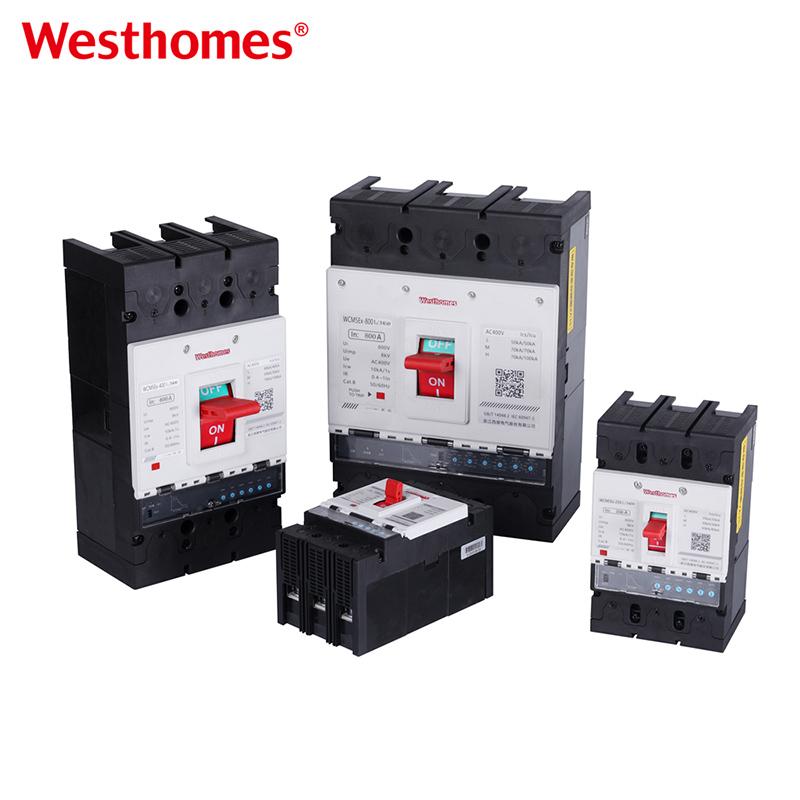
A frame size does not equal a fixed current. The frame sets the physical envelope and maximum breaking capacity rating, while the installed trip unit determines the rated operational current (In). A 250 A frame, for example, can be configured with a trip sensor calibrated anywhere within its adjustable span, allowing a single structural frame to adapt to multiple cable sizing tiers.
Specs buyers should compare
Specifying an MCCB from the nameplate current alone leaves essential engineering variables open. Evaluate and align these electrical parameters across every supplier proposal:
Frame Current vs. Rated Current (In)
Verify both the physical frame rating and the actual trip unit rating installed to prevent enclosure mismatches.
Voltage Ratings (Ue / Ui / Uimp)
Ensure the rated operational voltage (Ue), insulation voltage (Ui), and impulse withstand (Uimp) match system transients, especially in 690 V installations.
Breaking Capacities (Icu and Ics)
Differentiate between ultimate breaking capacity (Icu) and service breaking capacity (Ics). A high Ics percentage ensures the breaker remains functional after interrupting a short circuit.
Short-Time Withstand Current (Icw)
Verifies the thermal and mechanical duration an upstream breaker can hold a fault while downstream devices clear it.
Pole Configuration (3P vs. 4P)
Select 3-pole for standard 3-phase circuits or 4-pole where neutral isolation or dual-source transfer logic requires a switched neutral.
Trip Units and Modular Accessories
Choose between thermal-magnetic or electronic trip units, and configure shunt trips, undervoltage releases, auxiliary switches, and alarm contacts.
Standards Compliance and Approvals
Ensure conformity with IEC 60947-2 for international projects, alongside relevant regional certifications and local utility codes.
MCCB against MCB and ACB at a glance
Low-voltage circuit breakers span three major categories, each tailored to specific current ratings, fault duties, and board hierarchies:
| Category | MCB | MCCB | ACB |
|---|---|---|---|
| Typical Current | Up to approximately 125 A | Roughly 16 A to 1600 A across frame sizes | 630 A up to 6300 A at main distribution buses |
| Breaking Capacity | Typically 6 kA to 15 kA | Ranges from 25 kA up to 85 kA or 100 kA | Very high (typically 50 kA to 150 kA) for massive fault levels |
| Trip Characteristics | Fixed standard curves (Type B, C, or D) | Fixed thermal-magnetic or adjustable electronic units | Fully programmable electronic and digital trip controllers |
| Typical Location | Final branch circuits, lighting, and receptacles | Sub-distribution boards, motor feeders, and load centers | Main incoming switchgear and primary substations |
Operational overlap exists: a heavy-duty MCB can protect light sub-feeders, while an 800 A or 1200 A MCCB can serve as a main incomer. However, the final equipment selection must be determined by available fault energy, trip adjustability, and selective coordination rather than ampere rating alone.
Common selection mistakes
Sizing In strictly from load nameplate current
Neglecting cable current-carrying capacity, continuous loading factors, ambient temperatures, and conduit grouping derating factors.
Confusing Icu with Ics
Relying solely on a high ultimate breaking capacity (Icu) without confirming that the service capacity (Ics) allows the breaker to safely resume service after clearing a fault.
Over-specifying excessive kA ratings
Purchasing the highest breaking capacity available when the actual calculated prospective fault current at the board is substantially lower, inflating equipment costs without engineering benefit.
Overlooking selective coordination
Failing to coordinate time-current trip curves, causing upstream main breakers to trip ahead of downstream branch breakers during localized faults.
Omitting internal accessories and terminal hardware
Failing to specify shunt trips, auxiliary contacts, undervoltage releases, or terminal spreaders during ordering, creating installation delays during panel assembly.
What to put in the MCCB RFQ
System voltage, operational frequency, grounding scheme (TN, TT, IT), and application class (400 V or 690 V).
Required frame size current, rated operational current (In), and necessary trip adjustment thresholds.
Calculated prospective short-circuit current at the panel installation bus.
Target Icu and Ics values, including short-time withstand (Icw) where time-graded selectivity is required.
Pole count (3P or 4P), trip unit technology (thermal-magnetic or electronic), and protection functions.
Internal accessories: shunt release coils, undervoltage releases, auxiliary signal contacts, and alarm contacts.
Destination certifications (IEC, CE, UL), order volumes, and custom OEM/ODM packaging requirements.
Frequently asked questions
What is the difference between Icu and Ics?
Icu is the ultimate short-circuit breaking capacity: the breaker clears the fault but may experience internal contact erosion and require replacement. Ics is the service breaking capacity: after clearing a fault at this level, the breaker remains fully operational and safe to re-energize.
Can an MCCB replace an MCB on the same rail?
Physically, no. An MCCB has a significantly larger physical footprint and requires a rigid backplate or base mount rather than standard 35 mm DIN rails. Replacing an MCB with an MCCB requires verifying busbar capacity, panel depth, and cable termination spacing.
Is an electronic trip always better?
No. While electronic units offer fine-tuned dial settings, selective delay grading, and optional telemetry, thermal-magnetic trips are simpler, robust, cost-effective, and well-suited for straightforward sub-distribution panels.
What do 3P and 4P mean?
A 3P breaker switches the three active phases, leaving the neutral unswitched. A 4P breaker switches both the three phases and the neutral conductor, which is required in systems with dual utility/generator sources or specific isolation standards.
How does selectivity work between two breakers?
Selectivity ensures that only the breaker closest to the fault trips, leaving upstream feeders energized. This is achieved by coordinating short-time delay curves and current pickup thresholds between upstream and downstream devices.
Closing
The MCCB is the workhorse of the middle distribution layer: it carries heavy feeder currents, clears fault energies well beyond the capability of final-circuit MCBs, and allows engineers to tailor protection curves to specific conductors and downstream equipment. Select devices based on verified fault currents, required service capacities (Ics), and selective coordination plans rather than nominal catalog ratings.
Ready to specify an MCCB?
Send us your operating voltage, required frame size, rated current, prospective fault current, pole configuration, and accessory requirements. Our engineering team will provide coordinated model recommendations and a detailed commercial quote.
Keep reading
Standards referenced (verify current editions for the project)

--- END ---