Get quick appointment for technical support!

How to Size a Contactor for a Motor
Sep 17, 2026
Sizing a contactor is arithmetic before it is a catalog search. The catalog only becomes useful once three numbers are in hand, and those three numbers come from the motor rather than from the panel. Get them wrong and the frame that looks correct on paper will be the one that welds its contacts closed in service.
This walkthrough follows one motor through the whole calculation using the published figures from a three pole contactor range. The method works for any motor once the same three numbers are established.
The Three Numbers You Need First
A contactor is selected on the motor current, the system voltage, and the duty the motor performs. The first two are on the nameplate and the third is on the machine. Everything else in a selection follows from those three.
The Current, Not the Power
The nameplate gives a power figure in kilowatts and a current figure in amps. The current figure is the one the contactor is selected on. Power is useful for a cross-check, and it is not the starting point.
Where the nameplate current is missing or unreadable, the power can be converted at the actual voltage. Either way, the result is a starting point rather than the final figure, and it should be treated as an estimate until the nameplate is read.
The Utilization Category
The category describes what the motor does, and it changes the contactor requirement more than the current does. A motor driving a pump is not the same load as a motor driving a crusher, even at the same rating. The category is the number that separates the two.
Step 1: Read the Nameplate at the Actual Voltage
A motor nameplate lists more than one voltage, and the corresponding current differs for each. Reading the 230 V column when the machine runs at 380 V gives a current roughly 1.7 times too high, and the resulting contactor will be oversized.
Note the frequency as well, because a 50 Hz motor run at 60 Hz draws a different current. Where the machine has been rewound, the nameplate figure may no longer describe the winding, and a measured running current is the safer input.
Step 2: Find the Frame From the Published Table
A contactor table publishes the working current at each voltage alongside the power it can control, and the frame is read off that row. The range used here covers 9 A to 95 A across ten frames.
| Frame | Working current at 380 V | Thermal current | Motor power at 220 V | Motor power at 380 V |
| CJX2-09 | 8.5 A | 20 A | 2.2 kW | 4 kW |
| CJX2-12 | 11.5 A | 20 A | 3 kW | 5.5 kW |
| CJX2-18 | 16 A | 32 A | 4 kW | 11 kW |
| CJX2-25 | 22 A | 40 A | 5.5 kW | 15 kW |
| CJX2-32 | 30 A | 50 A | 7.5 kW | 18.5 kW |
| CJX2-40 | 37 A | 60 A | 11 kW | 18.5 kW |
| CJX2-50 | 44 A | 80 A | 15 kW | 22 kW |
| CJX2-65 | 60 A | 80 A | 18.5 kW | 30 kW |
| CJX2-80 | 72.5 A | 125 A | 22 kW | 37 kW |
| CJX2-95 | 85 A | 125 A | 25 kW | 45 kW |
Two things in that table are worth reading carefully. The working current at 380 V is lower than the working current at 660 V would be for the same frame, which is why the voltage column has to be matched rather than assumed. And the power column is not evenly spaced, so a 15 kW motor lands on one frame at 220 V and a different frame at 380 V.
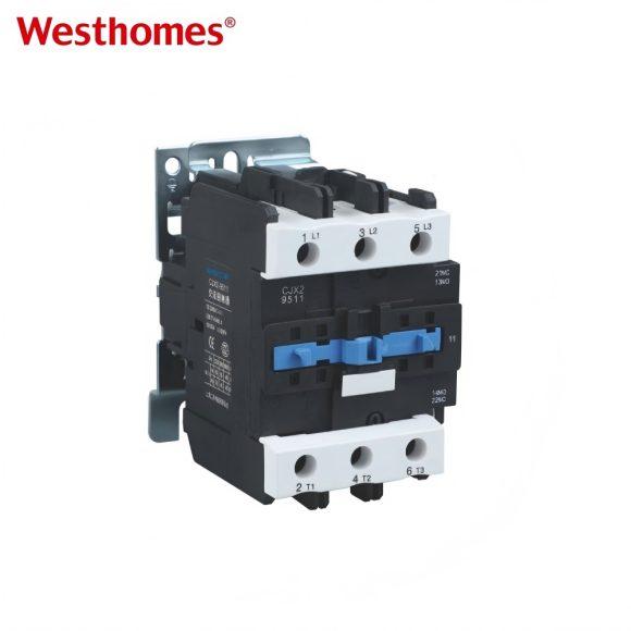
The three pole AC contactor range is published with the coil options listed for each frame.
Step 3: Check the Thermal Current Separately
The thermal current, written as Ith, is the current the contactor carries continuously without exceeding its temperature limit. It is always higher than the working current, and that gap is what allows for a panel that runs warm. The gap is not unlimited, and it is not there to cover a wrong frame.
A contactor inside a sealed enclosure sits in air that is warmer than the room, and the working current figure assumes an open installation. Where the panel has no ventilation, the frame is chosen one step up rather than at the exact current.
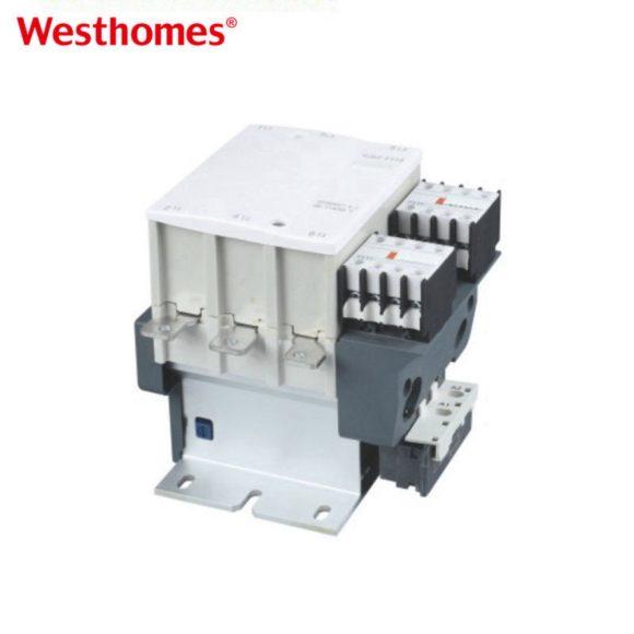
The same current figure feeds both the load calculation and the contactor selection, so one reading serves both.
Step 4: Check What the Coil Will Draw
The coil is part of the load on the control circuit, and its demand is not constant. The published figures for this range show an inrush between 76 and 230 VA depending on the frame, and a holding figure between 10 and 32 VA.
The inrush is the figure that decides the control transformer and the control fuse, because it occurs at the moment the coil energizes. Sizing a control circuit on the holding figure produces a transformer that dips on every start and a fuse that eventually fails.
| Frame group | Coil inrush | Coil holding | Ratio |
| CJX2-09 to 18 | 76 VA | 10 VA | 7.6 to 1 |
| CJX2-25 to 32 | 110 VA | 11 VA | 10 to 1 |
| CJX2-40 to 95 | 230 VA | 32 VA | 7.2 to 1 |
Step 5: Pair the Overload Relay
The relay is chosen from the motor current rather than from the contactor frame, and the two are then checked for physical pairing. A relay whose setting range does not bracket the motor current cannot protect it, whatever frame it mounts on.
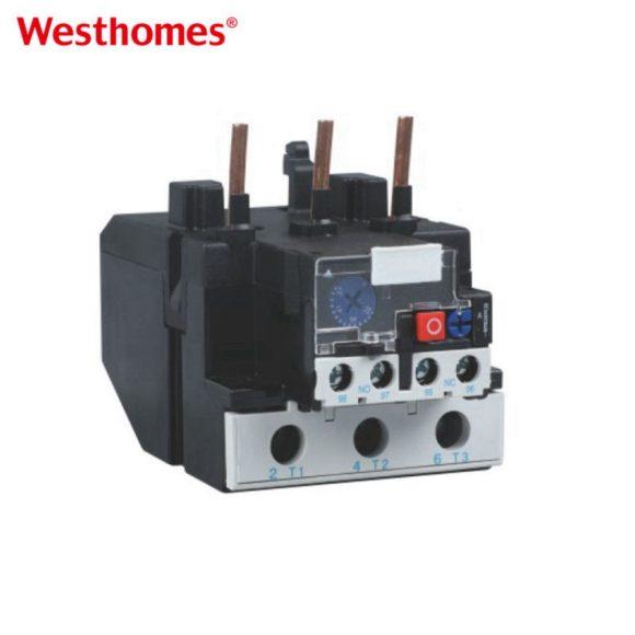
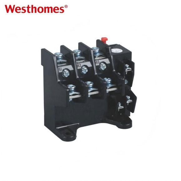
Each thermal overload relay type pairs with specific contactor frames, and setting it correctly is a separate exercise from selecting it.
A Worked Example
A 380 V three phase pump motor is rated 15 kW at 30 A on the nameplate. The duty is continuous running with a light start, so the category is the standard motor duty rather than a heavy one.
Reading the table at 30 A and 380 V gives the CJX2-32 frame, whose published power at that voltage is 18.5 kW. The thermal current for that frame is 50 A, which leaves room for the panel temperature. The coil for that frame draws 110 VA on pickup and 11 VA on hold.
The relay is then selected to bracket 30 A, and a setting range of 28 A to 36 A covers it with the setting placed at 30 A. The relay and the contactor mount together, and the pairing is published for the range.
Where the motor drives a load that starts under load rather than a pump, the same current leads to a larger frame. The current does not change and the requirement does.
Where the Calculation Goes Wrong
- Reading the nameplate voltage column that does not match the supply.
- Selecting on the power figure and never confirming the current.
- Ignoring the enclosure when reading the thermal current.
- Sizing the control transformer on the holding figure rather than the inrush.
- Choosing the overload relay to match the contactor frame instead of the motor current.
- Treating a rewound motor as though the nameplate still described it.
Most contactor failures trace back to one of those six rather than to a frame that was too small on paper. The frame is almost always adequate once the three numbers are right.
A contactor that has failed is worth reading before it is replaced, and the guide on motor burnout prevention covers what the failure pattern shows about the cause.
Summing Up
Contactor selection comes down to three numbers read from the motor and one table read at the right voltage. Take the current from the nameplate column that matches the supply, then read the frame from the working current at that voltage. Check the thermal current against the enclosure rather than against the open air figure. Size the control circuit on the coil inrush rather than on the holding figure, and pick the overload relay from the motor current rather than from the contactor frame. A selection built that way holds up whatever the motor is driving, and it takes less time than arguing about which frame looks right.

--- END ---
In this blog
Featured Articles
Get A Free Quote
