Get quick appointment for technical support!

DC Breakers for Solar: 1000V vs 1500V Selection Guide
Oct 25, 2026
Rooftop and small commercial arrays usually run at 1000 V DC; utility-scale and large commercial & industrial (C&I) plants have transitioned to 1500 V DC to cut cable size and minimize resistive losses. Market reports size the DC circuit breaker industry in the billions of dollars, driven by rapid growth in solar PV and battery storage systems (BESS). Yet the most critical mistake persists: installing an AC device or an undersized voltage-rated breaker on a live DC string and expecting it to clear a direct-current fault.
Why a DC breaker is a different device
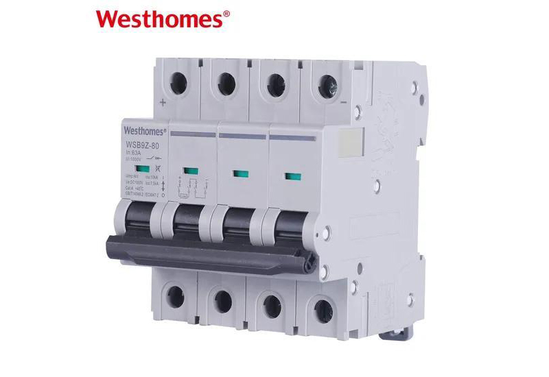
Alternating current (AC) crosses zero 100 or 120 times every second, allowing the electric arc to extinguish naturally at each crossing. Direct current (DC) never crosses zero. Once contacts part on an energized DC string, the arc continues to draw full circuit current unless the breaker actively stretches it using permanent magnetic blowout fields, accelerates it into heavy-duty deionizing arc chutes, and maintains a wider physical contact gap.
Furthermore, most DC breakers are strictly polarized, requiring positive and negative terminals to be landed exactly as marked on the frame. Reversing polarity neutralizes the magnetic arc-blowout effect, allowing the sustained plasma arc to bypass the chute and incinerate the housing.
The voltage rating is entirely DC-specific as well. A 1000 VAC rating provides no guarantee on a 1000 VDC circuit, and fitting an AC miniature circuit breaker on a photovoltaic string invites catastrophic contact welding and switchboard fires.
1000 V versus 1500 V systems
The voltage rating printed on the nameplate represents a safety ceiling, not an operating recommendation. System selection depends on array dimensions, string architecture, and central or string inverter MPPT voltage windows:
| Evaluation Point | 1000 V DC Architecture | 1500 V DC Architecture |
|---|---|---|
| Typical Role | Residential rooftop, small C&I arrays, and decentralized microgrids | Utility-scale solar farms, large C&I installations, and central BESS buses |
| Modules per String | Fewer modules in series, requiring a higher total number of parallel strings | Longer string configurations with up to 50% fewer parallel string runs |
| Current for Same Power | Higher operational current, requiring heavier conductor cross-sections | Lower operating current, reducing I²R thermal dissipation and cable costs |
| Typical Device | Modular DC MCB per string (1000 V class) | Heavy-duty DC MCCB on centralized collection buses (1500 V class) |
| Insulation & Spacing | Standard 1000 V creepage and clearance distances | Reinforced dielectric insulation, extended clearance, and elevated impulse testing |
| Fault Energy | Lower prospective short-circuit energy concentrated per string | Substantially higher available fault energy across consolidated busbars |
How to size the DC breaker
Sizing DC overcurrent protection requires meticulous attention to ambient thermal realities and source characteristics:
Cold-weather Voc calculation
Calculate maximum string open-circuit voltage at the site’s record-low design temperature using module temperature coefficients, ensuring it remains strictly below the breaker’s rated DC voltage. Photovoltaic cells generate peak Voc in sub-zero cold, not during peak summer heat.
Rated operational current (In)
Match rated current to string short-circuit currents (Isc) including continuous duty multipliers mandated by the inverter specifications and local electrical codes. Never upsize the breaker ampere rating merely to prevent nuisance trips on overloaded lines.
Pole count and voltage stacking
While a single pole can interrupt moderate DC voltages, higher 1000 V or 1500 V systems require multiple poles wired in series or factory-integrated multi-pole DC breakers configured with internal arc division.
Breaking capacity verification
Compare the device’s certified short-circuit interrupting capacity directly with the prospective DC fault current available from the combined strings or battery cells, rather than relying on surge kA ratings shown on lightning arresters.
Terminal polarity alignment
Strictly observe the marked positive (+) and negative (−) terminals during termination. Connecting a polarized DC breaker in reverse disrupts the magnetic flux direction and causes catastrophic failure during arc clearing.
Temperature and enclosure derating
Apply realistic derating factors for internal combiner-box and switchboard temperatures. Elevated solar irradiance and confined sheet-metal enclosures degrade breaker continuous current-carrying capacity.
Where a DC MCB ends and a DC MCCB starts
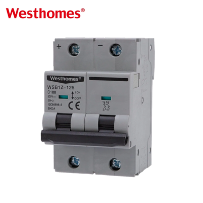
String-level protection remains compact: individual photovoltaic strings are protected by specialized DC MCBs sized to string voltage and current, typically mounted inside outdoor combiner boxes or decentralized junction enclosures.
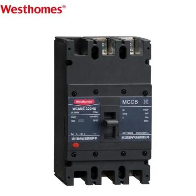
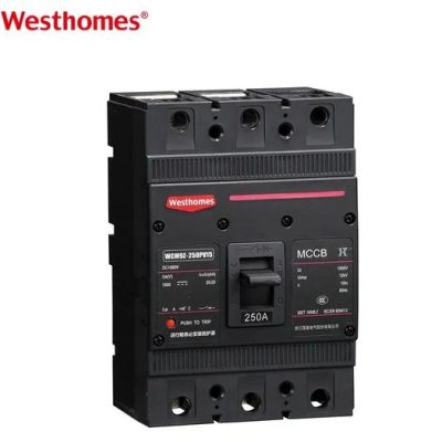
Once circuit topology aggregates multiple strings onto a main DC bus, battery rack, or central power conversion system (PCS) feeder carrying hundreds of amperes with severe prospective fault energy, the application transitions to a molded case circuit breaker (DC MCCB) engineered with reinforced frame architecture and elevated short-circuit withstand.
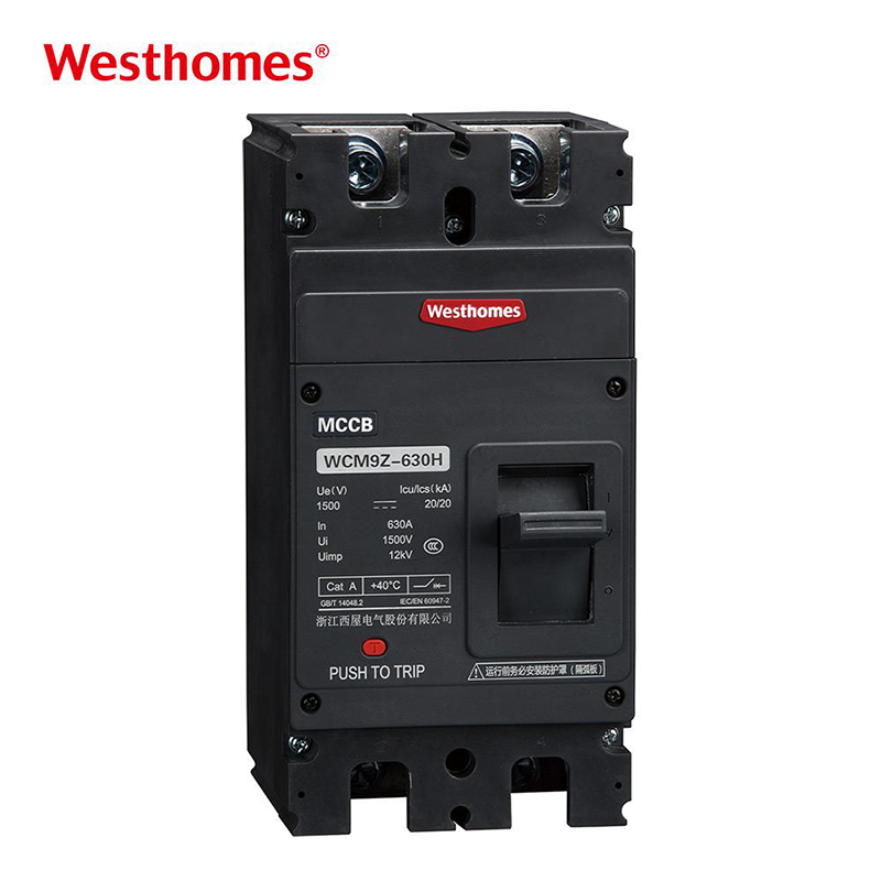
A battery storage system alters the physics of current flow: power flows bidirectionally, charging the cells from PV arrays or grid rectifiers and discharging back through the PCS. Overcurrent protective devices on battery circuits must be certified for bidirectional fault clearing, and selective coordination between string breakers, battery rack MCCBs, and master PCS isolators must ensure the device nearest the fault isolates first without shutting down the entire facility.
Surge and isolation sit alongside
Long, exposed outdoor DC cable runs act as antennae for atmospheric lightning and high-frequency switching transients. A dedicated photovoltaic surge protective device (DC SPD) with a maximum continuous operating voltage (Ucpv) calibrated safely above cold Voc clamps overvoltages before they penetrate inverter bridge electronics.
An SPD does not clear power-frequency overcurrents and requires its own dedicated backup protection and low-inductance grounding path. Concurrently, a load-break DC disconnect switch establishes a visible, lockable isolation point for maintenance personnel; designers must verify whether the disconnect switch is rated to interrupt live DC load currents or is strictly intended for isolating de-energized circuits.
Selection checklist
| Engineering Check | What to Record in Design Schedules |
|---|---|
| System Voltage | Lowest-temperature calculated Voc, inverter MPPT window, and selection of 1000 V or 1500 V class. |
| Device Type | DC MCB for string-level branch protection; DC MCCB for centralized buses, feeders, and battery racks. |
| Rated Current (In) | Calculated In versus operational string/bus current, continuous code safety factors, and enclosure heat derating. |
| Breaking Capacity | Available prospective DC short-circuit current versus certified Icu/Ics ratings at the operating voltage. |
| Terminal Polarity | Verified landed polarity against positive (+) and negative (−) markings to maintain magnetic arc blowout. |
| Storage Integration | Bidirectional fault duty certification, PCS isolation interfaces, and time-current selective coordination. |
| Auxiliary Equipment | DC SPD Ucpv ratings, backup overcurrent disconnects, load-break isolation capabilities, and status signaling. |
| Documentation | Manufacturer datasheets, factory compliance certificates, torque specifications, and site baseline test reports. |
Frequently asked questions
Can I stack two 1000 V breakers to reach 1500 V?
Only when the manufacturer explicitly designs, tests, and certifies the series pole arrangement. Stacking separate uncoordinated devices without a verified multi-pole rating leaves voltage distributed unevenly, causing one pole to absorb the entire fault voltage and fail.
Is a 1500 V device fine on a 1000 V system?
Voltage rating is a safety ceiling, so yes with respect to voltage. However, you must still verify that the rated operational current (In), breaking capacity, and pole configuration match the exact parameters of the 1000 V circuit.
Why does 1500 V use smaller cables?
For the same total power transfer, higher voltage reduces operational current proportionally. Lower current allows smaller conductor cross-sections, cutting I²R losses and balance-of-system copper costs across extensive utility arrays.
DC MCB or fuse for string protection?
Fuses are traditional for string reverse-current protection; resettable DC MCBs suit locations where immediate manual or automated reset after clearing a fault is preferred without stocking spare elements. Coordinate either choice with inverter limits and national codes.
Can an AC MCB protect a low-voltage DC circuit?
No. Even on lower-voltage DC circuits, the absence of natural zero crossings and lack of magnetic arc-blowout mechanisms allow the DC arc to persist, risking contact welding and housing fires. Always use devices certified for DC.
Closing
Work from cold-weather Voc down to operating In, select DC MCBs for string protection and DC MCCBs for the primary bus, and match every rating to realistic prospective fault currents and enclosure thermal conditions. The solar or storage plant that continues generating reliably after a disturbance is the one where every component was engineered specifically for the physics of direct current rather than carried over from an AC panel.
Ready to size your PV or storage DC protection?
Send us your system voltage, cold-calculated Voc, string or bus operating currents, prospective fault level, pole count, and target application (solar PV, BESS, or DC feeder). Our engineering team will match the appropriate DC MCB or DC MCCB models and provide a line-by-line quotation.
Keep reading
Standards referenced (verify current editions for the project)

--- END ---
Related Products