Get quick appointment for technical support!

What You Should Know About DC Circuit Breakers in Solar Combiner Boxes
Aug 28, 2026
solar combiner box DC circuit breaker
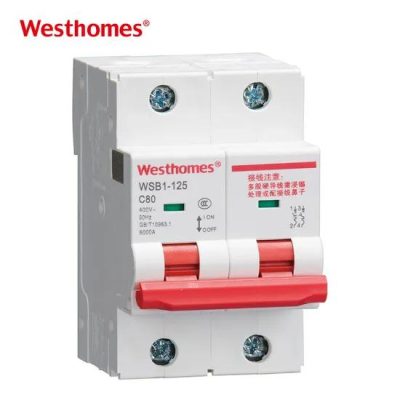
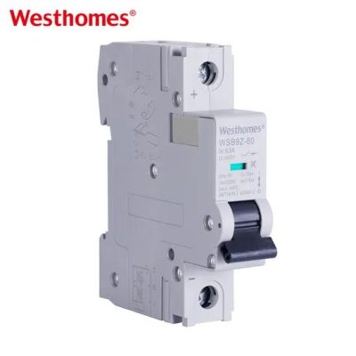
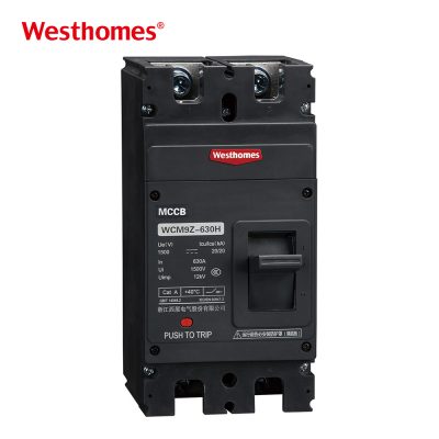
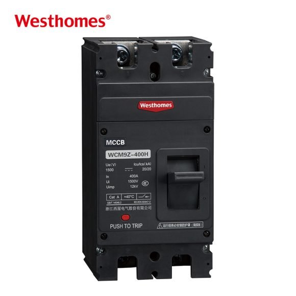
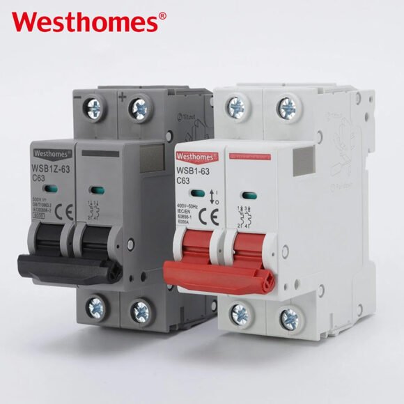
Solar combiner box DC circuit breakers serve as protective and isolation control equipment in photovoltaic power systems. These devices help prevent equipment damage and fires caused by overloads, short circuits, and reverse currents, with outer casings typically constructed from heat-resistant, flame-retardant polycarbonate or thermosetting plastics.
This article explains the functions, selection criteria, installation standards, common faults, and solutions for combiner box DC circuit breakers.
What Functions Do DC Circuit Breakers in Combiner Boxes Perform?
Overload and Short Circuit Protection
DC circuit breakers provide reliable overload and short circuit protection for solar arrays. When aging wiring, abnormal loads, or component failures push currents beyond safe rated values, the breaker opens the current path within milliseconds, which prevents high temperatures from causing fires or damaging solar inverters. Specialized arc-extinguishing tech handles the absence of natural zero-crossing points in direct current, which guarantees that the circuit interrupts safely during extreme fault conditions.
Reverse Current Prevention and System Isolation
In combiner boxes where multiple solar strings run in parallel, DC circuit breakers block reverse currents and isolate lines. When shading or faults cause one string to fall below the voltage of parallel strings, currents can flow backward, so the breaker stops this reverse current to protect modules. During routine maintenance or system inspections, operators can manually trip the breaker to achieve complete electrical isolation, which keeps personnel and equipment safe.
How to Select the Right DC Circuit Breaker for a Solar System?
Determining Voltage and Current Parameters
Matching voltage and current parameters serves as the primary step to ensure stable breaker operation. During selection, the rated operating voltage Ue must exceed the maximum open-circuit voltage Voc of the solar string at the lowest ambient temperature, which prevents high-voltage breakdown. The rated current In requires a calculation of 1.25 to 1.56 times the string maximum short-circuit current Isc to leave safety margins. Proper parameter configurations avoid accidental nuisance tripping while cutting off circuits rapidly during faults.
Evaluating Interrupting Capacity and Polarity Features
Evaluating the ultimate short-circuit interrupting capacity Icu along with polarity choices dictates system safety. The interrupting capacity must exceed the maximum short-circuit current that the solar system can generate, which ensures the breaker itself will not weld shut or burst during severe short circuits. Solar systems require choosing between polar and non-polar DC circuit breakers; if choosing a polar breaker, wiring must follow positive and negative markings strictly, as improper wiring leads to arc-extinguishing failure and severe flashover accidents.
Wiring and Installation Standards for Combiner Box DC Circuit Breakers
Following Polarity and Wiring Torque Rules
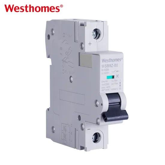
Connecting wiring terminals correctly and applying standard bolt torque ensures electrical connection reliability. For polar DC circuit breakers, installers must verify input wires from solar modules, which guarantees that polarity matches terminal markings on the breaker inlet. Using a torque screwdriver to tighten terminals according to manufacturer torque specifications prevents loose terminals from generating high contact resistance and heat, while avoiding over-tightening that damages internal mechanical structures.
Standardizing Layouts and Installing Protective Components
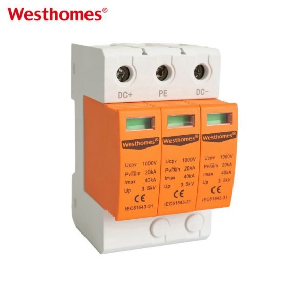
Reasonable spatial layouts and coordinated installation increase the overall protection efficacy of combiner boxes. Wiring requires UV-resistant DC dedicated cables that conform to solar standards such as H1Z2Z2-K, while keeping internal box lines neat without excessive bending. DC circuit breakers should coordinate with DC fuses and surge protective devices SPD inside the box, which creates multi-layered protection against overcurrent and overvoltage.
What Common Faults Might Occur?
Abnormal Tripping and Failure to Close
Abnormal tripping or failure to close stems from line overloads, short circuits, or mechanical wear. When actual system current exceeds the breaker set value, or when solar strings suffer from hidden short circuits, the breaker trips automatically; if manual closing fails after confirming no line faults exist, internal operating mechanisms or trip units may have sustained damage from repeated arc clearing, which requires replacing the equipment.
Terminal Overheating and Electric Arcing
Terminal overheating or internal arcing originates from poor contact or reversed polarity. Loose terminal bolts increase contact resistance, which melts terminal casings under high temperatures and heavy currents. When polar breakers are wired in reverse, disconnecting heavy currents prevents magnetic blowouts from extinguishing arcs, which creates continuous DC arcing that burns the breaker, requiring thermal imaging checks and terminal retightening for prevention.
Conclusion
Solar combiner box DC circuit breakers function as core protective components for safe solar system operation. Proper parameter selection, standard polarity installation, and regular maintenance checks prevent electrical fires and equipment damage, which improves long-term safety and power generation returns for solar stations.
Westhomesele provides options suitable for solar combiner boxes, and inquiries are welcome on the homepage.
Frequently Asked Questions
01Can AC MCBs replace solar DC MCBs?
No. Direct current lacks natural zero-crossing points, making arcs hard to extinguish. AC breakers on DC circuits cause continuous arcing that destroys equipment.
02Why must polarity be observed on DC breakers?
Polar DC breakers use internal magnets to pull arcs into the quenching chamber. Reversed polarity pushes the arc backward, causing arc failure or explosion.
03How do you calculate a DC breaker’s rated current?
Multiply the solar string’s maximum short-circuit current (Isc) by 1.25 to 1.56. This safety margin prevents nuisance trips during peak sunlight and high heat.
04What causes frequent DC breaker tripping?
Overcurrents exceeding the rating, hidden line shorts or ground faults, loose terminals causing high resistance/heat, or internal mechanical fatigue.
05How often should DC breakers be inspected?
Every 6 to 12 months. Inspect for loose terminal torque, casing discoloration or melting, and thermal hot spots under load.
Build a Safer Electrical System
Discuss ratings, application conditions, and protection requirements with the Westhomesele team.

--- END ---
In this blog
Featured Articles
Get A Free Quote