Get quick appointment for technical support!

How to Choose a Circuit Breaker for a Battery Energy Storage System
Sep 06, 2026
BESS circuit breaker
A battery energy storage system, also known as BESS, stores electrical energy in battery packs and releases it to loads or the grid when needed. It is widely used in solar energy storage, commercial and industrial energy storage, and utility-scale energy storage projects. Circuit breakers protect batteries, cables, and other equipment by interrupting the circuit when overloads, short circuits, or abnormal currents occur. Because battery energy storage systems often operate at high DC voltages and large currents, circuit breakers should be selected according to actual system parameters.
This article explains circuit breaker sizing requirements, the differences between MCBs and MCCBs, mechanical and installation requirements, and the process for selecting a suitable circuit breaker.
Why Do Battery Energy Storage Systems Require Dedicated Circuit Breakers?
Battery energy storage systems often operate at high DC voltages and can produce large short circuit currents. Batteries can also continue supplying energy after a fault occurs. Unlike AC current, DC current does not pass through a natural zero point during each cycle, which makes DC arcs more difficult to extinguish. If a standard AC circuit breaker is used directly in a DC battery system, it may fail to interrupt the fault current safely. Battery energy storage systems therefore require circuit breakers with suitable DC voltage ratings, breaking capacities, and arc extinguishing performance so that overload and short circuit protection can operate reliably.
What Are the Main Circuit Breaker Sizing Requirements?
Select battery-energy-storage-system circuit breakers based on key electrical parameters and full operating conditions, not just normal current.
Rated Operating Voltage
The rated operating voltage of the circuit breaker should be equal to or higher than the highest voltage that may appear in the energy storage system. The nominal battery voltage alone is not sufficient for selection.
Rated Current
Rated current determines whether the circuit breaker can continuously carry the normal charging and discharging current of the battery system. Selection should consider the maximum charging and discharging power of the PCS, the continuous current of the battery pack, cable current carrying capacity, and ambient temperature.
Short Circuit Breaking Capacity
Breaking capacity directly affects whether the circuit breaker can interrupt a battery fault safely. Battery packs generally have low internal resistance, which means they can produce very high current immediately after a short circuit occurs. The rated short circuit breaking capacity of the circuit breaker should therefore be equal to or higher than the prospective short circuit current at the installation point.
Number of Poles and Wiring Method
DC circuit breakers are commonly available with 1P, 2P, 3P, and 4P configurations. The required number of poles depends on system voltage, grounding arrangement, and the wiring method specified by the manufacturer. In high-voltage DC systems, several poles may be connected in series so that the circuit breaker can interrupt a higher DC voltage.
Trip Characteristics
Trip characteristics determine how quickly a circuit breaker operates during overload and short circuit conditions. Battery energy storage systems may experience temporary current changes during charging, discharging, or PCS startup. The selected trip characteristic should provide fast fault protection while reducing unwanted tripping during normal operation. MCBs commonly use B, C, or D trip curves, while MCCBs may provide adjustable thermal magnetic or electronic trip settings. Selection should consider maximum continuous current, temporary current peaks, and protection coordination requirements.
Comparison Between MCBs and MCCBs in Battery Energy Storage Systems
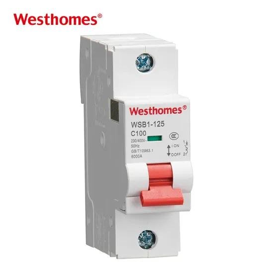
MCBs and MCCBs provide overload and short-circuit protection yet differ in performance and installation, serving different circuit positions in battery energy storage systems.
Current and Voltage Range
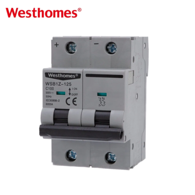
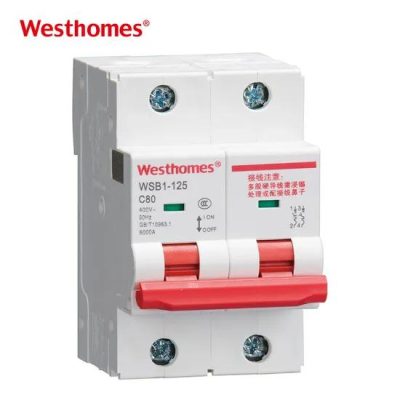
MCBs are commonly used in lower current energy storage circuits, including monitoring equipment, control circuits, small battery modules, and auxiliary DC loads. Their compact construction makes them suitable for DIN rail installation. MCCBs support a wider range of current ratings and are often available with higher DC operating voltage ratings. For battery cabinet outputs and main energy storage circuits that carry several hundred amperes or more, MCCBs usually provide more suitable rating options. The final selection should always follow the DC ratings specified by the manufacturer.
Breaking Capacity
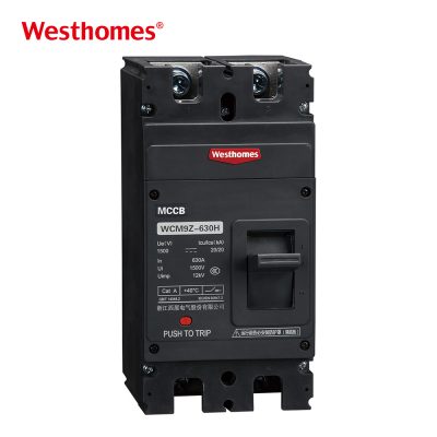
MCBs are smaller devices and generally provide lower short circuit breaking capacity than larger MCCBs, which makes them more suitable for branch circuits where the prospective fault current is lower. MCCBs use larger contacts and arc extinguishing structures and usually provide higher breaking capacities. This makes them suitable for locations close to battery packs or DC busbars where fault currents may be higher. For either type, the breaking capacity should be checked at the actual DC operating voltage instead of using AC breaking data.
Protection Functions and Adjustability
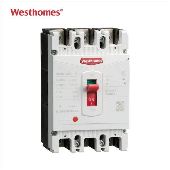
MCBs usually use fixed thermal magnetic trip characteristics. They are simple to install and maintain, although their protection settings offer limited adjustment. MCCBs can be equipped with adjustable thermal magnetic trip units or electronic trip units. Some models allow long delay, short delay, and instantaneous protection settings to be adjusted. This allows MCCBs to work more effectively in larger battery storage systems where coordination between upstream and downstream protective devices is required. Settings can be matched to battery characteristics, busbars, and cable ratings to improve selective protection.
Quick Comparison of MCBs and MCCBs
| Comparison Item | MCB | MCCB |
|---|---|---|
| Typical application | Small branch circuits and auxiliary circuits | Battery cabinets, combining circuits, and main circuits |
| Rated current | Usually lower | Usually higher |
| Breaking capacity | Relatively lower | Relatively higher |
| Trip settings | Mostly fixed | Adjustable settings are available |
| Installation method | Commonly mounted on a 35 mm DIN rail | Commonly mounted on a panel |
| Installation space | Smaller | Larger |
| Cost | Lower | Higher |
| Protection coordination | Limited | More flexible |
Mechanical and Installation Requirements
| Item | Common Requirements |
|---|---|
| Installation method | MCBs commonly use 35 mm DIN rails, while MCCBs are commonly panel mounted |
| Terminal type | Copper conductors, cable lugs, or busbar connections depending on the model |
| Cable capacity | Selected according to terminal specifications and rated current |
| Terminal torque | Tightened according to the torque value in N·m specified by the manufacturer |
| Mechanical life | Depends on the product series and operating mechanism |
| Electrical life | Depends on operating voltage, current, and switching conditions |
| Protection level | Circuit breaker bodies often provide basic finger protection, while enclosure IP rating depends on the cabinet |
| Ambient temperature | Manufacturer operating temperature limits and derating curves should be checked |
| Installation orientation | Follow the mounting positions permitted by the manufacturer |
| Installation clearance | High current applications should allow sufficient space for heat dissipation and electrical clearance |
After confirming the electrical parameters of the circuit breaker, mechanical dimensions, installation methods, terminal specifications, and environmental conditions should also be checked. These factors affect internal wiring, cabinet layout, heat dissipation, and long-term operating reliability, particularly in battery cabinets where installation space is limited and current levels remain high for extended periods.
How to Choose the Right Circuit Breaker?
Select battery-energy-storage circuit breakers by system conditions, electrical parameters and standards for safe current-carrying and fault interruption.
Rated Operating Voltage
Choose circuit breakers with rated voltage ≥ the system’s maximum DC voltage, not merely nominal battery voltage. Calculate maximum voltage from series-connected cells, cell max charging voltage and system upper limit.
Rated Current
Rated current handles continuous battery charge-discharge current. Factor in PCS max power, pack current, cable capacity and ambient temperature. Select ratings above continuous operating current yet adequate to protect downstream devices; apply manufacturer-specified derating for high-load continuous operation.
Short Circuit Breaking Capacity
Batteries generate large short-circuit currents due to low internal resistance. Breaking capacity must meet or exceed prospective short-circuit current at the installation point. Calculate fault current from battery traits, cable impedance and system layout to avoid contact welding and arc-interruption failure.
Number of Poles and Wiring Method
DC breakers come in 1P-4P types. Pole count depends on system voltage, grounding and manufacturer rules. Series poles raise DC interruption voltage; observe polarity and line-load direction, as extra poles do not inherently boost working voltage.
Trip Characteristics
Trip curves set overload and short-circuit response speed. Pick settings for fast fault clearance and avoidance of nuisance tripping amid normal current transients. MCBs adopt B/C/D curves; MCCBs offer adjustable trip functions, matched to continuous current, transient peaks and protection coordination.
Conclusion
Selecting a circuit breaker for a battery energy storage system requires consideration of maximum DC voltage, continuous operating current, prospective short circuit current, breaking capacity, number of poles, trip characteristics, and installation conditions. Matching the circuit breaker with the battery, cables, and other protective devices helps improve system safety, operating reliability, and maintenance efficiency.
Westhomesele offers a wide range of circuit breakers suitable for battery energy storage systems, with different materials, electrical ratings, and protection functions available for different applications. Visit our homepage to learn more or contact us for product information.
Frequently Asked Questions
01Can a standard AC circuit breaker be used in a battery energy storage system?
A standard AC circuit breaker should not be used unless the manufacturer clearly states that the product is rated for the required DC voltage and breaking conditions.
02Should a battery energy storage system use an MCB or an MCCB?
A DC MCB is generally suitable for lower current branch circuits, while an MCCB is more suitable for battery cabinets, combining circuits, and main circuits with higher current levels.
03Is a higher circuit breaker current rating always better?
No. An excessively high current rating can reduce overload protection for cables and equipment. The rating should match the continuous operating current and cable current carrying capacity.
04Why does DC breaking capacity matter in battery energy storage systems?
Battery short circuits can produce very high fault currents, while DC arcs do not have natural current zero points. Sufficient DC breaking capacity allows the circuit breaker to interrupt the fault safely.
05What parameters should be checked when selecting a circuit breaker for battery energy storage?
Check the rated DC voltage, rated current, DC short circuit breaking capacity, number of poles, trip characteristics, wiring method, and installation conditions.
Build a Safer Electrical System
Discuss ratings, application conditions, and protection requirements with the Westhomesele team.
See Breaking Capacity in 250A Molded Case Circuit Breakers for a deeper dive into breaking capacity.

--- END ---
In this blog
Featured Articles
Get A Free Quote
Related Products